HP Pavilion 15-bk000 Maintenance and Service Guide - Page 39
CAUTION, Release the zero insertion force ZIF connector
 |
View all HP Pavilion 15-bk000 manuals
Add to My Manuals
Save this manual to your list of manuals |
Page 39 highlights
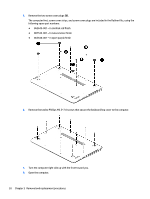
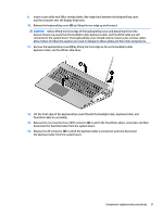
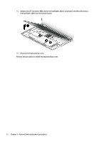
9. Insert a case utility tool (1) or similar plastic, flat-edged tool between the keyboard/top cover and the computer near the display hinge area. 10. Release the keyboard/top cover (2) by lifting the rear edge up and forward. CAUTION: Before lifting the front edge of the keyboard/top cover and detaching it from the base enclosure, be aware that the backlight cable, keyboard cable, and TouchPad cable are still connected to the system board. The keyboard/top cover should only be moved as far as these cables allow. Failure to follow this caution can result in damage to these cables and their main components. 11. Remove the keyboard/top cover (3) by lifting the front edge as far as the backlight cable, keyboard cable, and TouchPad cable allow. 12. Lift the front edge of the keyboard/top cover (1) until the backlight cable, keyboard cable, and TouchPad cable are accessible. 13. Release the zero insertion force (ZIF) connector (2) to which the TouchPad cable is connected, and then disconnect the TouchPad cable from the system board. 14. Release the ZIF connector (3) to which the keyboard cable is connected, and then disconnect the keyboard cable from the system board. Component replacement procedures 31
-
 1
1 -
2
-
3
-
4
-
5
-
6
-
7
-
8
-
9
-
10
-
11
-
12
-
13
-
14
-
15
-
16
-
17
-
18
-
19
-
20
-
21
-
22
-
23
-
24
-
25
-
26
-
27
-
28
-
29
-
30
-
31
-
32
-
33
-
 34
34 -
 35
35 -
 36
36 -
 37
37 -
 38
38 -
 39
39 -
 40
40 -
 41
41 -
 42
42 -
 43
43 -
 44
44 -
45
-
46
-
47
-
48
-
49
-
50
-
51
-
52
-
53
-
54
-
55
-
56
-
57
-
58
-
59
-
60
-
61
-
62
-
63
-
64
-
65
-
66
-
67
-
68
-
69
-
70
-
71
-
72
-
73
-
74
-
75
-
76
-
77
-
78
-
79
-
80
-
81
-
82
-
83
-
84
 |
 |
