HP Pavilion 15-bk000 Maintenance and Service Guide - Page 52
Fan/heat sink assembly
 |
View all HP Pavilion 15-bk000 manuals
Add to My Manuals
Save this manual to your list of manuals |
Page 52 highlights
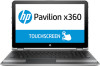
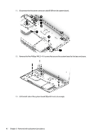
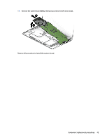
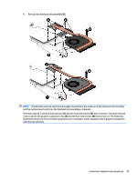
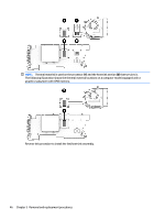
Fan/heat sink assembly Description For use only on computer models equipped with a graphics subsystem with discrete video memory For use only on computer models equipped with a graphics subsystem with UMA video memory Spare part number 863970-001 862523-001 Before removing the fan/heat sink assembly, follow these steps: 1. Turn off the computer. If you are unsure whether the computer is off or in Hibernation, turn the computer on, and then shut it down through the operating system. 2. Disconnect the power from the computer by unplugging the power cord from the computer. 3. Disconnect all external devices from the computer. 4. Remove the base enclosure (see Keyboard/top cover on page 28). 5. Disconnect the battery cable from the system board (see Battery on page 33). 6. Disconnect the WLAN module antenna cables from the WLAN module (see WLAN module on page 37). 7. Remove the system board (see System board on page 40). Remove the fan/heat sink assembly: 1. Turn the system board upside down with the front toward you. 2. Disconnect the fan cable (1) from the system board. NOTE: The number of screws used to secure the fan/heat sink assembly to the system board varies by computer model. Computer models equipped with a graphics subsystem with discrete memory require eight screws. Computer models equipped with a graphics subsystem with UMA memory require four screws. 3. Loosen the seven or four Phillips PM2.0×6.5 captive screws (2) that secure the fan/heat sink assembly to the system board. 44 Chapter 5 Removal and replacement procedures
-
 1
1 -
2
-
3
-
4
-
5
-
6
-
7
-
8
-
9
-
10
-
11
-
12
-
13
-
14
-
15
-
16
-
17
-
18
-
19
-
20
-
21
-
22
-
23
-
24
-
25
-
26
-
27
-
28
-
29
-
30
-
31
-
32
-
33
-
34
-
35
-
36
-
37
-
38
-
39
-
40
-
41
-
42
-
43
-
44
-
45
-
46
-
 47
47 -
 48
48 -
 49
49 -
 50
50 -
 51
51 -
 52
52 -
 53
53 -
 54
54 -
 55
55 -
 56
56 -
 57
57 -
58
-
59
-
60
-
61
-
62
-
63
-
64
-
65
-
66
-
67
-
68
-
69
-
70
-
71
-
72
-
73
-
74
-
75
-
76
-
77
-
78
-
79
-
80
-
81
-
82
-
83
-
84
 |
 |