HP Pavilion 15-bk000 Maintenance and Service Guide - Page 49
to which the power button board cable is connected, and then disconnect
 |
View all HP Pavilion 15-bk000 manuals
Add to My Manuals
Save this manual to your list of manuals |
Page 49 highlights
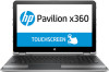
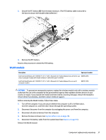
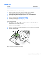
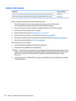
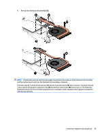
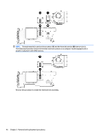
1. Turn off the computer. If you are unsure whether the computer is off or in Hibernation, turn the computer on, and then shut it down through the operating system. 2. Disconnect the power from the computer by unplugging the power cord from the computer. 3. Disconnect all external devices from the computer. 4. Remove the base enclosure (see Keyboard/top cover on page 28). 5. Disconnect the battery cable from the system board (see Battery on page 33). 6. Disconnect the WLAN module antenna cables from the WLAN module (see WLAN module on page 37). NOTE: When replacing the system board, be sure that the following components are removed from the defective system board and installed on the replacement system board. ● Memory module (see Memory module on page 47) ● WLAN module (see WLAN module on page 37) ● Fan/heat sink assembly (see Fan/heat sink assembly on page 44) Remove the system board: 1. Release the ZIF connector (1) to which the display panel cable is connected, and then disconnect the display panel cable from the system board. 2. Detach the display panel cable (2) from the system board. (The display panel cable is attached to the system board with double-sided adhesive.) 3. Release the ZIF connector (3) to which the webcam/microphone module cable is connected, and then disconnect the webcam/microphone module cable from the system board. 4. Detach the grounding tape (4) that secures the webcam/microphone module cable to the system board. 5. Release the ZIF connector (5) to which the power button board cable is connected, and then disconnect the power button board cable from the system board. 6. Detach the power button board cable (6) from the fan. (The power button board cable is attached to the fan with double-sided adhesive.) 7. Release the ZIF connector (7) to which the connector board cable is connected, and then disconnect the connector board cable from the system board. 8. Release the ZIF connector (8) to which the hard drive cable is connected, and then disconnect the hard drive cable from the system board. 9. Disconnect the speaker cable (9) from the system board. 10. Disconnect the RTC battery cable (10) from the system board. Component replacement procedures 41
-
 1
1 -
2
-
3
-
4
-
5
-
6
-
7
-
8
-
9
-
10
-
11
-
12
-
13
-
14
-
15
-
16
-
17
-
18
-
19
-
20
-
21
-
22
-
23
-
24
-
25
-
26
-
27
-
28
-
29
-
30
-
31
-
32
-
33
-
34
-
35
-
36
-
37
-
38
-
39
-
40
-
41
-
42
-
43
-
 44
44 -
 45
45 -
 46
46 -
 47
47 -
 48
48 -
 49
49 -
 50
50 -
 51
51 -
 52
52 -
 53
53 -
 54
54 -
55
-
56
-
57
-
58
-
59
-
60
-
61
-
62
-
63
-
64
-
65
-
66
-
67
-
68
-
69
-
70
-
71
-
72
-
73
-
74
-
75
-
76
-
77
-
78
-
79
-
80
-
81
-
82
-
83
-
84
 |
 |