HP Pavilion 17-e100 Pavilion 17 TouchSmart Notebook PC Pavilion 17 Notebook PC - Page 87
until it rests at an angle., Lift the right side of the system board
 |
View all HP Pavilion 17-e100 manuals
Add to My Manuals
Save this manual to your list of manuals |
Page 87 highlights
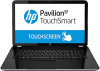
(3) USB board ribbon cable (4) Power connector cable 7. Remove the three Phillips PM2.5×7.0 screws (5) that secure the system board to the base enclosure. 8. Lift the right side of the system board (1) until it rests at an angle. 9. Remove the system board (2) by sliding it up and to the right an angle. Reverse this procedure to install the system board. Component replacement procedures 77
-
 1
1 -
2
-
3
-
4
-
5
-
6
-
7
-
8
-
9
-
10
-
11
-
12
-
13
-
14
-
15
-
16
-
17
-
18
-
19
-
20
-
21
-
22
-
23
-
24
-
25
-
26
-
27
-
28
-
29
-
30
-
31
-
32
-
33
-
34
-
35
-
36
-
37
-
38
-
39
-
40
-
41
-
42
-
43
-
44
-
45
-
46
-
47
-
48
-
49
-
50
-
51
-
52
-
53
-
54
-
55
-
56
-
57
-
58
-
59
-
60
-
61
-
62
-
63
-
64
-
65
-
66
-
67
-
68
-
69
-
70
-
71
-
72
-
73
-
74
-
75
-
76
-
77
-
78
-
79
-
80
-
81
-
 82
82 -
 83
83 -
 84
84 -
 85
85 -
 86
86 -
 87
87 -
 88
88 -
 89
89 -
 90
90 -
 91
91 -
 92
92 -
93
-
94
-
95
-
96
-
97
-
98
-
99
-
100
-
101
-
102
-
103
-
104
-
105
-
106
-
107
-
108
-
109
-
110
-
111
-
112
-
113
-
114
-
115
-
116
-
117
-
118
-
119
-
120
 |
 |

(3)
USB board ribbon cable
(4)
Power connector cable
7.
Remove the three Phillips PM2.5×7.0 screws
(5)
that secure the system board to the
base enclosure.
8.
Lift the right side of the system board
(1)
until it rests at an angle.
9.
Remove the system board
(2)
by sliding it up and to the right an angle.
Reverse this procedure to install the system board.
Component replacement procedures
77