HP Pavilion dv5-2100 HP Pavilion dv5 Entertainment PC - Maintenance and Servic - Page 65
The WLAN module tilts up.
 |
View all HP Pavilion dv5-2100 manuals
Add to My Manuals
Save this manual to your list of manuals |
Page 65 highlights
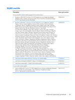
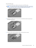
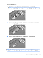
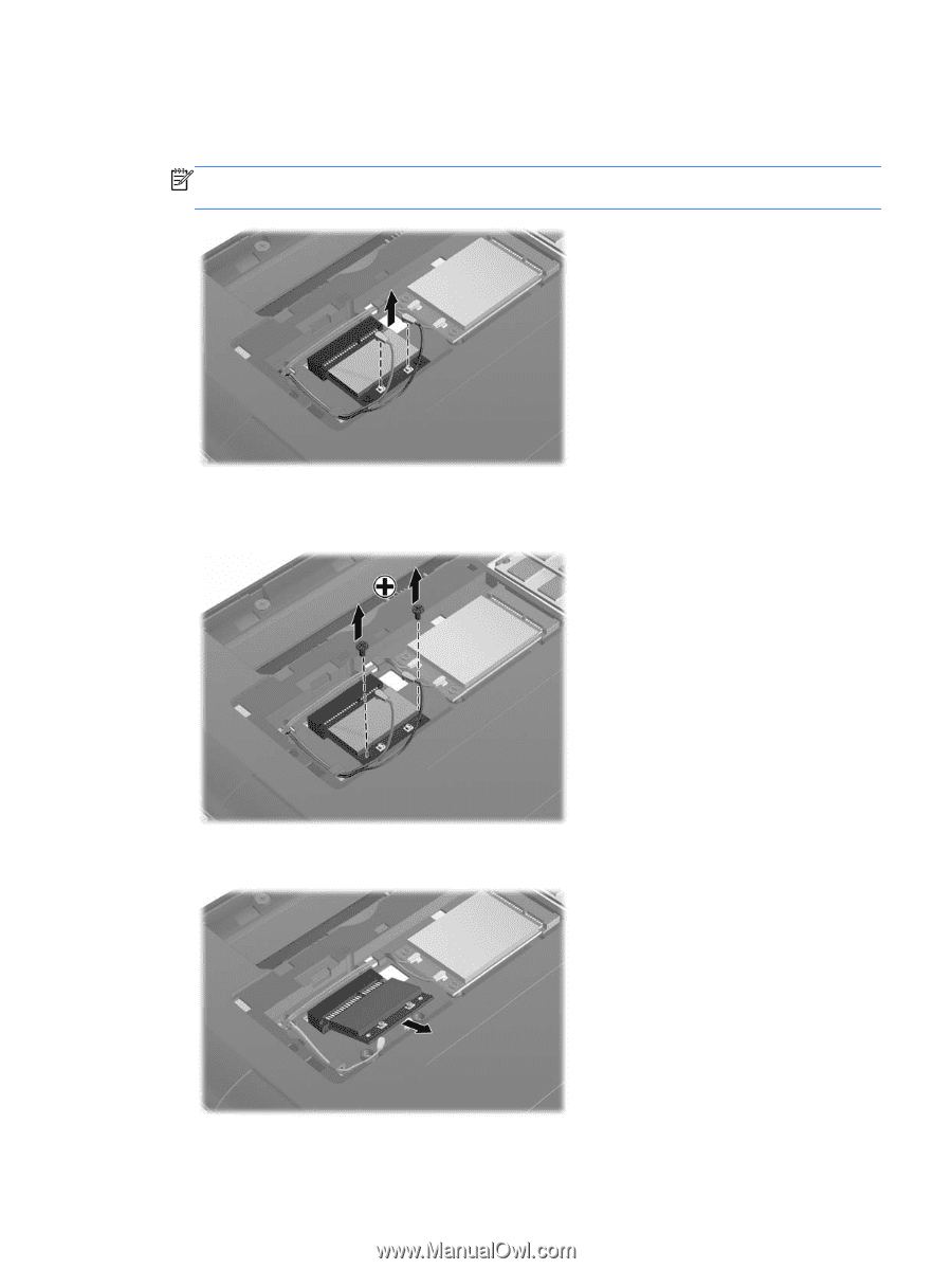
Remove the WLAN module: 1. Disconnect the WLAN antenna cables from the terminals on the WLAN module. NOTE: The 1/black WLAN antenna cable is connected to the WLAN module 1/Main terminal. The 2/gray WLAN antenna cable is connected to the WLAN module 2/Aux terminal. 2. Remove the two Phillips PM2.0×4.0 screws that secure the WLAN module to the system board. (The WLAN module tilts up.) 3. Remove the WLAN module by pulling the module away from the slot at an angle. Component replacement procedures 55
-
 1
1 -
2
-
3
-
4
-
5
-
6
-
7
-
8
-
9
-
10
-
11
-
12
-
13
-
14
-
15
-
16
-
17
-
18
-
19
-
20
-
21
-
22
-
23
-
24
-
25
-
26
-
27
-
28
-
29
-
30
-
31
-
32
-
33
-
34
-
35
-
36
-
37
-
38
-
39
-
40
-
41
-
42
-
43
-
44
-
45
-
46
-
47
-
48
-
49
-
50
-
51
-
52
-
53
-
54
-
55
-
56
-
57
-
58
-
59
-
 60
60 -
 61
61 -
 62
62 -
 63
63 -
 64
64 -
 65
65 -
 66
66 -
 67
67 -
 68
68 -
 69
69 -
 70
70 -
71
-
72
-
73
-
74
-
75
-
76
-
77
-
78
-
79
-
80
-
81
-
82
-
83
-
84
-
85
-
86
-
87
-
88
-
89
-
90
-
91
-
92
-
93
-
94
-
95
-
96
-
97
-
98
-
99
-
100
-
101
-
102
-
103
-
104
-
105
-
106
-
107
-
108
-
109
-
110
-
111
-
112
-
113
-
114
-
115
-
116
-
117
-
118
-
119
-
120
-
121
-
122
-
123
-
124
-
125
-
126
-
127
-
128
-
129
-
130
-
131
-
132
-
133
-
134
-
135
 |
 |
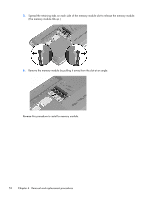
Remove the WLAN module:
1.
Disconnect the WLAN antenna cables from the terminals on the WLAN module.
NOTE:
The 1/black WLAN antenna cable is connected to the WLAN module 1/Main terminal.
The 2/gray WLAN antenna cable is connected to the WLAN module 2/Aux terminal.
2.
Remove the two Phillips PM2.0×4.0 screws that secure the WLAN module to the system board.
(The WLAN module tilts up.)
3.
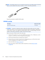
Remove the WLAN module by pulling the module away from the slot at an angle.
Component replacement procedures
55