HP Pavilion dv5-2100 HP Pavilion dv5 Entertainment PC - Maintenance and Servic - Page 83
Optical drive cable, Remove the Phillips PM2.0×3.0 screw
 |
View all HP Pavilion dv5-2100 manuals
Add to My Manuals
Save this manual to your list of manuals |
Page 83 highlights
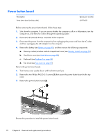
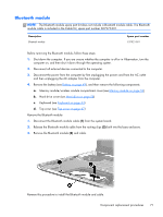
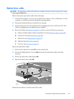
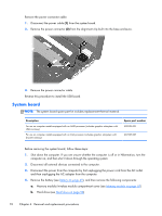
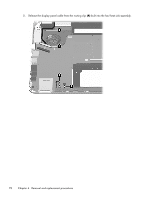
Optical drive cable NOTE: The optical drive cable and bracket are included in the base enclosure spare part kit, spare part number 606884-001. Before removing the optical drive cable, follow these steps: 1. Shut down the computer. If you are unsure whether the computer is off or in Hibernation, turn the computer on, and then shut it down through the operating system. 2. Disconnect all external devices connected to the computer. 3. Disconnect the power from the computer by first unplugging the power cord from the AC outlet and then unplugging the AC adapter from the computer. 4. Remove the battery (see Battery on page 49), and then remove the following components: a. Memory module/wireless module compartment cover (see Memory module on page 50) b. Hard drive cover (see Hard drive on page 58) c. Optical drive (see Optical drive on page 63) d. Keyboard (see Keyboard on page 64) e. Top cover (see Top cover on page 67) Remove the optical drive cable: 1. Disconnect the optical drive cable (1) from the system board. 2. Remove the Phillips PM2.0×3.0 screw (2) that secures the optical drive cable to the base enclosure. 3. Remove the optical drive cable bracket (3). 4. Remove the optical drive cable (4). Reverse this procedure to install the optical drive cable. Component replacement procedures 73
-
 1
1 -
2
-
3
-
4
-
5
-
6
-
7
-
8
-
9
-
10
-
11
-
12
-
13
-
14
-
15
-
16
-
17
-
18
-
19
-
20
-
21
-
22
-
23
-
24
-
25
-
26
-
27
-
28
-
29
-
30
-
31
-
32
-
33
-
34
-
35
-
36
-
37
-
38
-
39
-
40
-
41
-
42
-
43
-
44
-
45
-
46
-
47
-
48
-
49
-
50
-
51
-
52
-
53
-
54
-
55
-
56
-
57
-
58
-
59
-
60
-
61
-
62
-
63
-
64
-
65
-
66
-
67
-
68
-
69
-
70
-
71
-
72
-
73
-
74
-
75
-
76
-
77
-
 78
78 -
 79
79 -
 80
80 -
 81
81 -
 82
82 -
 83
83 -
 84
84 -
 85
85 -
 86
86 -
 87
87 -
 88
88 -
89
-
90
-
91
-
92
-
93
-
94
-
95
-
96
-
97
-
98
-
99
-
100
-
101
-
102
-
103
-
104
-
105
-
106
-
107
-
108
-
109
-
110
-
111
-
112
-
113
-
114
-
115
-
116
-
117
-
118
-
119
-
120
-
121
-
122
-
123
-
124
-
125
-
126
-
127
-
128
-
129
-
130
-
131
-
132
-
133
-
134
-
135
 |
 |