HP Pavilion dv6-3100 HP Pavilion dv6 Entertainment PC - Maintenance and Servic - Page 75
Display assembly, Disconnect the TouchScreen cable
 |
View all HP Pavilion dv6-3100 manuals
Add to My Manuals
Save this manual to your list of manuals |
Page 75 highlights
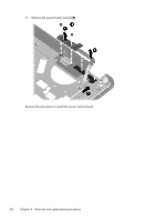
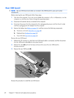
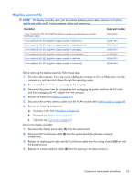
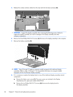
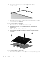
Display assembly NOTE: The display assembly spare part kit includes a display panel cable, webcam/microphone module and cable, and 2 wireless antenna cables and transceivers. Description 15.6-in TouchScreen HD, LED, BrightView display assembly in brushed aluminum (includes TouchScreen cable) 15.6-in traditional HD, LED, BrightView display assembly in black cherry 15.6-in traditional HD, LED, BrightView display assembly in brushed aluminum 15.6-in traditional HD, LED, BrightView display assembly in champagne 15.6-in traditional HD, LED, BrightView display assembly in midnight blue 15.6-in traditional HD, LED, BrightView display assembly in shell white 15.6-in traditional HD, LED, BrightView display assembly in Sonoma red Spare part number 595132-001 603647-001 595131-001 603650-001 615932-001 603648-001 603649-001 Before removing the display assembly, follow these steps: 1. Shut down the computer. If you are unsure whether the computer is off or in Hibernation, turn the computer on, and then shut it down through the operating system. 2. Disconnect all external devices connected to the computer. 3. Disconnect the power from the computer by first unplugging the power cord from the AC outlet and then unplugging the AC adapter from the computer. 4. Remove the battery (see Battery on page 43). 5. Disconnect the wireless antenna cables from the WLAN module (see WLAN module on page 49). 6. Remove the following components: a. Accessory cover (see Hard drive on page 44) b. Keyboard (see Keyboard on page 53) c. Top cover (see Top cover on page 56) Remove the display assembly: 1. Disconnect the display panel cable (1) from the system board. 2. Disconnect the TouchScreen cable (2) from the system board (TouchScreen computer models only). 3. Release the display panel cable and the TouchScreen cable from the routing channel (3) built into the base enclosure. 4. Release the wireless antenna cables (4) from the opening in the base enclosure. Component replacement procedures 65
-
 1
1 -
2
-
3
-
4
-
5
-
6
-
7
-
8
-
9
-
10
-
11
-
12
-
13
-
14
-
15
-
16
-
17
-
18
-
19
-
20
-
21
-
22
-
23
-
24
-
25
-
26
-
27
-
28
-
29
-
30
-
31
-
32
-
33
-
34
-
35
-
36
-
37
-
38
-
39
-
40
-
41
-
42
-
43
-
44
-
45
-
46
-
47
-
48
-
49
-
50
-
51
-
52
-
53
-
54
-
55
-
56
-
57
-
58
-
59
-
60
-
61
-
62
-
63
-
64
-
65
-
66
-
67
-
68
-
69
-
 70
70 -
 71
71 -
 72
72 -
 73
73 -
 74
74 -
 75
75 -
 76
76 -
 77
77 -
 78
78 -
 79
79 -
 80
80 -
81
-
82
-
83
-
84
-
85
-
86
-
87
-
88
-
89
-
90
-
91
-
92
-
93
-
94
-
95
-
96
-
97
-
98
-
99
-
100
-
101
-
102
-
103
-
104
-
105
-
106
-
107
-
108
-
109
-
110
-
111
-
112
-
113
-
114
-
115
-
116
-
117
-
118
-
119
-
120
-
121
-
122
-
123
-
124
-
125
-
126
-
127
-
128
-
129
-
130
 |
 |