HP Pavilion dv6-3100 HP Pavilion dv6 Entertainment PC - Maintenance and Servic - Page 86
System board, RTC battery see
 |
View all HP Pavilion dv6-3100 manuals
Add to My Manuals
Save this manual to your list of manuals |
Page 86 highlights
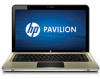
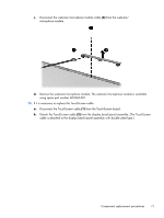
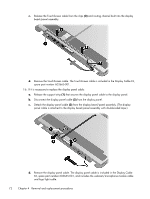
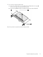
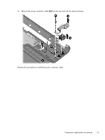
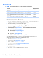
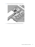
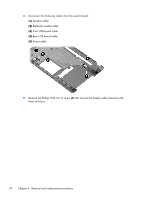
System board NOTE: The system board spare part kit includes replacement thermal material. Description For use on computer models equipped with a graphics subsystem with discrete memory and the HD5650 chipset For use on computer models equipped with a graphics subsystem with discrete memory and the HD5470 chipset For use on computer models equipped with a graphics subsystem with discrete memory and the HD545V chipset For use on computer models equipped with a graphics subsystem with UMA memory Spare part number 603939-001 595133-001 615906-001 595135-001 Before removing the system board, follow these steps: 1. Shut down the computer. If you are unsure whether the computer is off or in Hibernation, turn the computer on, and then shut it down through the operating system. 2. Disconnect all external devices connected to the computer. 3. Disconnect the power from the computer by first unplugging the power cord from the AC outlet and then unplugging the AC adapter from the computer. 4. Remove the battery (see Battery on page 43), and then remove the following components: a. Hard drive (see Hard drive on page 44) b. Optical drive (see Optical drive on page 51) c. Keyboard (see Keyboard on page 53) d. Top cover (see Top cover on page 56) e. Display assembly (see Display assembly on page 65) When replacing the system board, be sure that the following components are removed from the defective system board and installed on the replacement system board: ● RTC battery (see RTC battery on page 47) ● Memory modules (see Memory module on page 48) ● WLAN module (see WLAN module on page 49) ● Fan/heat sink assembly (see Fan/heat sink assembly on page 80) ● Processor (see Processor on page 83) Remove the system board: 1. Turn the base enclosure upside down, with the front toward you. 76 Chapter 4 Removal and replacement procedures
-
 1
1 -
2
-
3
-
4
-
5
-
6
-
7
-
8
-
9
-
10
-
11
-
12
-
13
-
14
-
15
-
16
-
17
-
18
-
19
-
20
-
21
-
22
-
23
-
24
-
25
-
26
-
27
-
28
-
29
-
30
-
31
-
32
-
33
-
34
-
35
-
36
-
37
-
38
-
39
-
40
-
41
-
42
-
43
-
44
-
45
-
46
-
47
-
48
-
49
-
50
-
51
-
52
-
53
-
54
-
55
-
56
-
57
-
58
-
59
-
60
-
61
-
62
-
63
-
64
-
65
-
66
-
67
-
68
-
69
-
70
-
71
-
72
-
73
-
74
-
75
-
76
-
77
-
78
-
79
-
80
-
 81
81 -
 82
82 -
 83
83 -
 84
84 -
 85
85 -
 86
86 -
 87
87 -
 88
88 -
 89
89 -
 90
90 -
 91
91 -
92
-
93
-
94
-
95
-
96
-
97
-
98
-
99
-
100
-
101
-
102
-
103
-
104
-
105
-
106
-
107
-
108
-
109
-
110
-
111
-
112
-
113
-
114
-
115
-
116
-
117
-
118
-
119
-
120
-
121
-
122
-
123
-
124
-
125
-
126
-
127
-
128
-
129
-
130
 |
 |