HP Pavilion dv6-3100 HP Pavilion dv6 Entertainment PC - Maintenance and Servic - Page 80
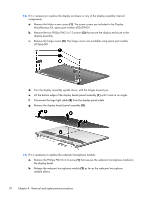
Remove the Phillips PM2.0×4.0 screw, Remove the display bezel/panel assembly
 |
View all HP Pavilion dv6-3100 manuals
Add to My Manuals
Save this manual to your list of manuals |
Page 80 highlights
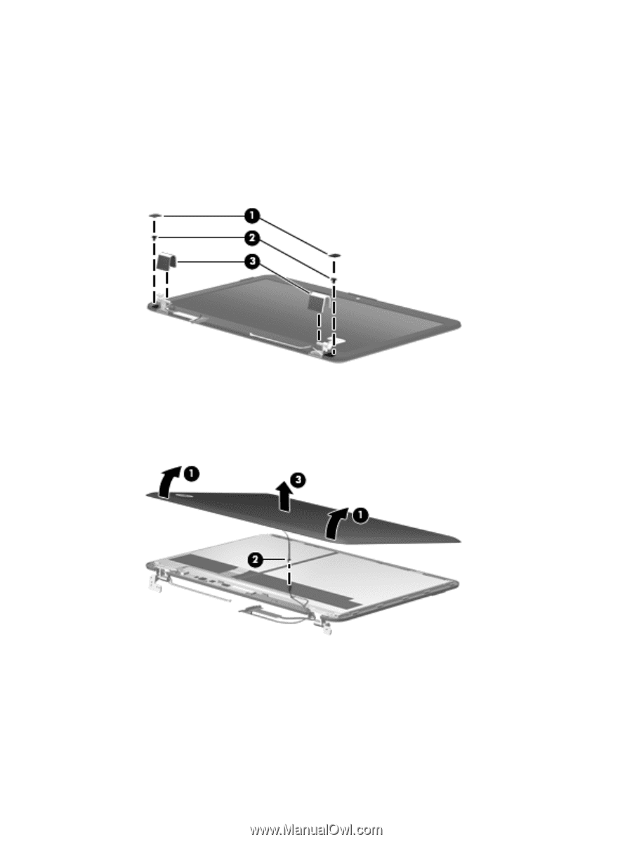
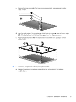
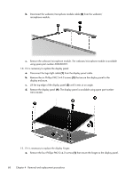
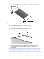
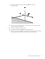
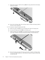
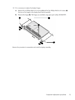
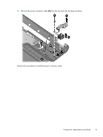
13. If it is necessary to replace the display enclosure or any of the display assembly internal components: a. Remove the Mylar screw covers (1). The screw covers are included in the Display Miscellaneous Kit, spare part number 603659-001. b. Remove the two Phillips PM2.5×7.0 screws (2) that secure the display enclosure to the display assembly. c. Remove the hinge covers (3). The hinge covers are available using spare part number 603666-001. d. Turn the display assembly upside down, with the hinges toward you. e. Lift the bottom edge of the display bezel/panel assembly (1) until it rests at an angle. f. Disconnect the logo light cable (2) from the display panel cable. g. Remove the display bezel/panel assembly (3). 14. If it is necessary to replace the webcam/microphone module: a. Remove the Phillips PM2.0×4.0 screw (1) that secures the webcam/microphone module to the display bezel. b. Release the webcam/microphone module (2) as far as the webcam/microphone module allows. 70 Chapter 4 Removal and replacement procedures
-
 1
1 -
2
-
3
-
4
-
5
-
6
-
7
-
8
-
9
-
10
-
11
-
12
-
13
-
14
-
15
-
16
-
17
-
18
-
19
-
20
-
21
-
22
-
23
-
24
-
25
-
26
-
27
-
28
-
29
-
30
-
31
-
32
-
33
-
34
-
35
-
36
-
37
-
38
-
39
-
40
-
41
-
42
-
43
-
44
-
45
-
46
-
47
-
48
-
49
-
50
-
51
-
52
-
53
-
54
-
55
-
56
-
57
-
58
-
59
-
60
-
61
-
62
-
63
-
64
-
65
-
66
-
67
-
68
-
69
-
70
-
71
-
72
-
73
-
74
-
 75
75 -
 76
76 -
 77
77 -
 78
78 -
 79
79 -
 80
80 -
 81
81 -
 82
82 -
 83
83 -
 84
84 -
 85
85 -
86
-
87
-
88
-
89
-
90
-
91
-
92
-
93
-
94
-
95
-
96
-
97
-
98
-
99
-
100
-
101
-
102
-
103
-
104
-
105
-
106
-
107
-
108
-
109
-
110
-
111
-
112
-
113
-
114
-
115
-
116
-
117
-
118
-
119
-
120
-
121
-
122
-
123
-
124
-
125
-
126
-
127
-
128
-
129
-
130
 |
 |