HP Pavilion g7 HP Pavilion g7 Notebook PC - Maintenance and Service Guide - Page 66
TouchPad cable, part number 640212-001
 |
View all HP Pavilion g7 manuals
Add to My Manuals
Save this manual to your list of manuals |
Page 66 highlights
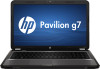
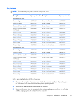
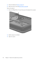
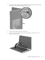
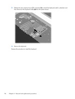
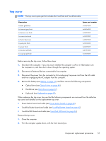
3. Remove the 12 Phillips PM2.5×7.0 screws that secure the top cover to the computer. 4. Remove the two Phillips PM2.5×7.0 screws (1) in the hard drive bay and the three Phillips PM2.5×6.0 screws (2) in the battery bay that secure the top cover to the computer. 5. Turn the computer right-side up, with the front toward you. 6. Open the computer. 7. Release the ZIF connectors to which the following cables are attached, and then disconnect the cables from the system board: ● Power button board cable (1) (included with the power button board spare part kit, spare part number 640212-001) ● TouchPad cable (2) (included in the Cable Kit, spare part number 640206-001) ● TouchPad button board cable (3) (included with the TouchPad button board spare part kit, spare part number 640214-001) 58 Chapter 4 Removal and replacement procedures
-
 1
1 -
2
-
3
-
4
-
5
-
6
-
7
-
8
-
9
-
10
-
11
-
12
-
13
-
14
-
15
-
16
-
17
-
18
-
19
-
20
-
21
-
22
-
23
-
24
-
25
-
26
-
27
-
28
-
29
-
30
-
31
-
32
-
33
-
34
-
35
-
36
-
37
-
38
-
39
-
40
-
41
-
42
-
43
-
44
-
45
-
46
-
47
-
48
-
49
-
50
-
51
-
52
-
53
-
54
-
55
-
56
-
57
-
58
-
59
-
60
-
 61
61 -
 62
62 -
 63
63 -
 64
64 -
 65
65 -
 66
66 -
 67
67 -
 68
68 -
 69
69 -
 70
70 -
 71
71 -
72
-
73
-
74
-
75
-
76
-
77
-
78
-
79
-
80
-
81
-
82
-
83
-
84
-
85
-
86
-
87
-
88
-
89
-
90
-
91
-
92
-
93
-
94
-
95
-
96
-
97
-
98
-
99
-
100
-
101
-
102
-
103
-
104
-
105
-
106
-
107
-
108
-
109
-
110
-
111
-
112
-
113
-
114
-
115
-
116
-
117
-
118
-
119
-
120
-
121
-
122
-
123
-
124
-
125
-
126
-
127
-
128
-
129
-
130
 |
 |
