HP Pavilion g7 HP Pavilion g7 Notebook PC - Maintenance and Service Guide - Page 87
Fan and heat sink
 |
View all HP Pavilion g7 manuals
Add to My Manuals
Save this manual to your list of manuals |
Page 87 highlights
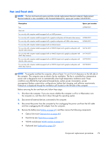
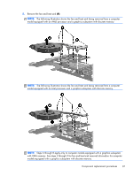
Fan and heat sink NOTE: The fan and heat sink spare part kits include replacement thermal material. Replacement thermal material is also available in the Thermal Material Kit, spare part number 634433-001. Description Spare part number Fan 639460-001 Heat sink: For use only with computer models equipped with an AMD processor: For use only with computer models equipped with a graphics subsystem with discrete video memory 639462-001 For use only with computer models equipped with a graphics subsystem with UMA video memory 639463-001 For use only with computer models equipped with an Intel processor: For use only with computer models equipped with an HM65 chipset and a graphics subsystem with discrete video memory 641141-001 For use only with computer models equipped with an HM65 chipset and a graphics subsystem with UMA video memory 641140-001 For use only with computer models equipped with an HM55 chipset and a graphics subsystem with discrete video memory 637190-001 For use only with computer models equipped with an HM55 chipset and a graphics subsystem with UMA video memory 637189-001 NOTE: To properly ventilate the computer, allow at least 7.6 cm (3 in) of clearance on the left side of the computer. The computer uses an electric fan for ventilation. The fan is controlled by a temperature sensor and is designed to turn on automatically when high temperature conditions exist. These conditions are affected by high external temperatures, system power consumption, power management/battery conservation configurations, battery fast charging, and software requirements. Exhaust air is displaced through the ventilation grill located on the left side of the computer. Before removing the fan and heat sink, follow these steps: 1. Shut down the computer. If you are unsure whether the computer is off or in Hibernation, turn the computer on, and then shut it down through the operating system. 2. Disconnect all external devices connected to the computer. 3. Disconnect the power from the computer by first unplugging the power cord from the AC outlet and then unplugging the AC adapter from the computer. 4. Remove the battery (see Battery on page 44), and then remove the following components: ● Optical drive (see Optical drive on page 45) ● Hard drive (see Hard drive on page 47) ● WLAN module (see WLAN module on page 51) ● Keyboard (see Keyboard on page 53) Component replacement procedures 79
-
 1
1 -
2
-
3
-
4
-
5
-
6
-
7
-
8
-
9
-
10
-
11
-
12
-
13
-
14
-
15
-
16
-
17
-
18
-
19
-
20
-
21
-
22
-
23
-
24
-
25
-
26
-
27
-
28
-
29
-
30
-
31
-
32
-
33
-
34
-
35
-
36
-
37
-
38
-
39
-
40
-
41
-
42
-
43
-
44
-
45
-
46
-
47
-
48
-
49
-
50
-
51
-
52
-
53
-
54
-
55
-
56
-
57
-
58
-
59
-
60
-
61
-
62
-
63
-
64
-
65
-
66
-
67
-
68
-
69
-
70
-
71
-
72
-
73
-
74
-
75
-
76
-
77
-
78
-
79
-
80
-
81
-
 82
82 -
 83
83 -
 84
84 -
 85
85 -
 86
86 -
 87
87 -
 88
88 -
 89
89 -
 90
90 -
 91
91 -
 92
92 -
93
-
94
-
95
-
96
-
97
-
98
-
99
-
100
-
101
-
102
-
103
-
104
-
105
-
106
-
107
-
108
-
109
-
110
-
111
-
112
-
113
-
114
-
115
-
116
-
117
-
118
-
119
-
120
-
121
-
122
-
123
-
124
-
125
-
126
-
127
-
128
-
129
-
130
 |
 |
