HP Pavilion g7 HP Pavilion g7 Notebook PC - Maintenance and Service Guide - Page 86
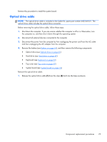
Reverse this procedure to install the optical drive connector and cable
 |
View all HP Pavilion g7 manuals
Add to My Manuals
Save this manual to your list of manuals |
Page 86 highlights
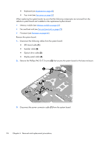
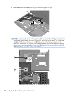
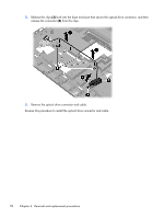
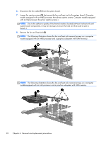
2. Release the clips (3) built into the base enclosure that secure the optical drive connector, and then release the connector (4) from the clips. 3. Remove the optical drive connector and cable. Reverse this procedure to install the optical drive connector and cable. 78 Chapter 4 Removal and replacement procedures
-
 1
1 -
2
-
3
-
4
-
5
-
6
-
7
-
8
-
9
-
10
-
11
-
12
-
13
-
14
-
15
-
16
-
17
-
18
-
19
-
20
-
21
-
22
-
23
-
24
-
25
-
26
-
27
-
28
-
29
-
30
-
31
-
32
-
33
-
34
-
35
-
36
-
37
-
38
-
39
-
40
-
41
-
42
-
43
-
44
-
45
-
46
-
47
-
48
-
49
-
50
-
51
-
52
-
53
-
54
-
55
-
56
-
57
-
58
-
59
-
60
-
61
-
62
-
63
-
64
-
65
-
66
-
67
-
68
-
69
-
70
-
71
-
72
-
73
-
74
-
75
-
76
-
77
-
78
-
79
-
80
-
 81
81 -
 82
82 -
 83
83 -
 84
84 -
 85
85 -
 86
86 -
 87
87 -
 88
88 -
 89
89 -
 90
90 -
 91
91 -
92
-
93
-
94
-
95
-
96
-
97
-
98
-
99
-
100
-
101
-
102
-
103
-
104
-
105
-
106
-
107
-
108
-
109
-
110
-
111
-
112
-
113
-
114
-
115
-
116
-
117
-
118
-
119
-
120
-
121
-
122
-
123
-
124
-
125
-
126
-
127
-
128
-
129
-
130
 |
 |

2.
Release the clips
(3)
built into the base enclosure that secure the optical drive connector, and then
release the connector
(4)
from the clips.
3.
Remove the optical drive connector and cable.
Reverse this procedure to install the optical drive connector and cable.
78
Chapter 4
Removal and replacement procedures