HP Pavilion g7 HP Pavilion g7 Notebook PC - Maintenance and Service Guide - Page 82
Remove the Philllips PM2.5×7.0 screw, Display panel cable
 |
View all HP Pavilion g7 manuals
Add to My Manuals
Save this manual to your list of manuals |
Page 82 highlights
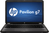
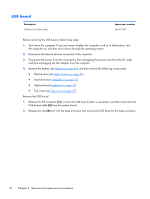
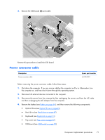
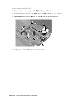
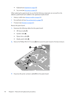
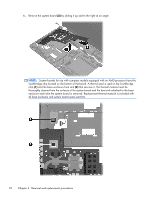
● Keyboard (see Keyboard on page 53) ● Top cover (see Top cover on page 57) When replacing the system board, be sure that the following components are removed from the defective system board and installed on the replacement system board: ● Memory module (see Memory module on page 50) ● Fan and heat sink (see Fan and heat sink on page 79) ● Processor (see Processor on page 86) Remove the system board: 1. Disconnect the following cables from the system board: ● LED board cable (1) ● Speaker cable (2) ● Optical drive cable (3) ● Display panel cable (4) 2. Remove the Philllips PM2.5×7.0 screw (5) that secures the system board to the base enclosure. 3. Disconnect the power connector cable (1) from the system board. 74 Chapter 4 Removal and replacement procedures
-
 1
1 -
2
-
3
-
4
-
5
-
6
-
7
-
8
-
9
-
10
-
11
-
12
-
13
-
14
-
15
-
16
-
17
-
18
-
19
-
20
-
21
-
22
-
23
-
24
-
25
-
26
-
27
-
28
-
29
-
30
-
31
-
32
-
33
-
34
-
35
-
36
-
37
-
38
-
39
-
40
-
41
-
42
-
43
-
44
-
45
-
46
-
47
-
48
-
49
-
50
-
51
-
52
-
53
-
54
-
55
-
56
-
57
-
58
-
59
-
60
-
61
-
62
-
63
-
64
-
65
-
66
-
67
-
68
-
69
-
70
-
71
-
72
-
73
-
74
-
75
-
76
-
 77
77 -
 78
78 -
 79
79 -
 80
80 -
 81
81 -
 82
82 -
 83
83 -
 84
84 -
 85
85 -
 86
86 -
 87
87 -
88
-
89
-
90
-
91
-
92
-
93
-
94
-
95
-
96
-
97
-
98
-
99
-
100
-
101
-
102
-
103
-
104
-
105
-
106
-
107
-
108
-
109
-
110
-
111
-
112
-
113
-
114
-
115
-
116
-
117
-
118
-
119
-
120
-
121
-
122
-
123
-
124
-
125
-
126
-
127
-
128
-
129
-
130
 |
 |
