HP Presario 1600 Presario 1600XL Series Maintenance and Service Guide - Page 55
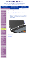
Hard Drive
 |
View all HP Presario 1600 manuals
Add to My Manuals
Save this manual to your list of manuals |
Page 55 highlights
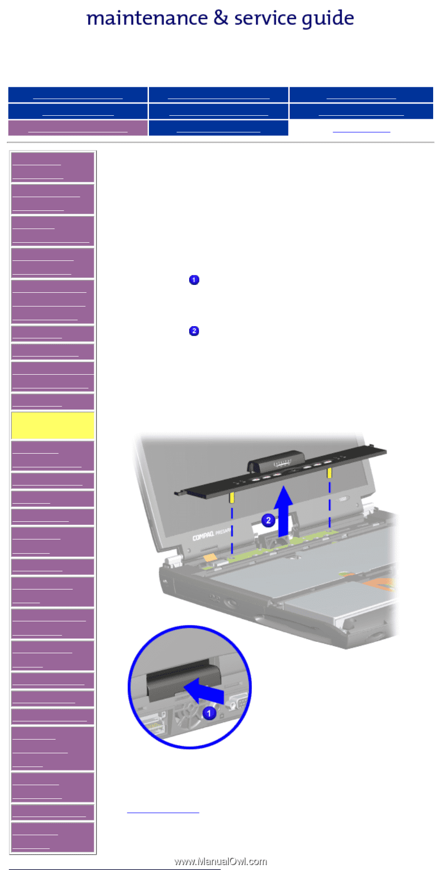
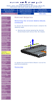
Presario 1600 Series Models: 1600T, 1600-XL140, 1600-XL141, 1600-XL142, 1600-XL143, 1600-XL144, 1600-XL145, 1600-XL146, and 1600-XL147 Before You Begin Specifications Removal Sequence Product Description Battery Operations Troubleshooting Parts Catalog Pin Assignments MSG Index Removal Sequence Electrostatic Discharge Service Considerations Cables and Connectors Preparing the Computer for Disassembly QuikDock Battery Pack Palmrest Cover with TouchPad Keyboard Status/Internet Zone Cover Internet Button Board Heatspreader Modem Hard Drive DisqPlay Module Processor CD or DVD Drive Display Panel Assembly Upper CPU Cover Fan Assembly RTC Battery Diskette Drive Voltage Converter Board Speaker Assembly System Board Memory Module Removal Sequence Removing the Status/Internet Zone Cover, continued 5. Turn the unit right side up and open the display assembly. 6. Lift up one corner of the Status/Internet Zone Cover . 7. Push forward from the back (center piece) to release the snaps on the Status/Internet Zone Cover . 8. Remove Status/Internet Zone Cover from the chassis. To replace the status panel assembly, reverse the previous procedures. Previous Step
-
 1
1 -
2
-
3
-
4
-
5
-
6
-
7
-
8
-
9
-
10
-
11
-
12
-
13
-
14
-
15
-
16
-
17
-
18
-
19
-
20
-
21
-
22
-
23
-
24
-
25
-
26
-
27
-
28
-
29
-
30
-
31
-
32
-
33
-
34
-
35
-
36
-
37
-
38
-
39
-
40
-
41
-
42
-
43
-
44
-
45
-
46
-
47
-
48
-
49
-
 50
50 -
 51
51 -
 52
52 -
 53
53 -
 54
54 -
 55
55 -
 56
56 -
 57
57 -
 58
58 -
 59
59 -
 60
60 -
61
-
62
-
63
-
64
-
65
-
66
-
67
-
68
-
69
-
70
-
71
-
72
-
73
-
74
-
75
-
76
-
77
-
78
-
79
-
80
-
81
-
82
-
83
-
84
-
85
-
86
-
87
-
88
-
89
-
90
-
91
-
92
 |
 |