HP Presario 1600 Presario 1600XL Series Maintenance and Service Guide - Page 80
RTC Battery
 |
View all HP Presario 1600 manuals
Add to My Manuals
Save this manual to your list of manuals |
Page 80 highlights
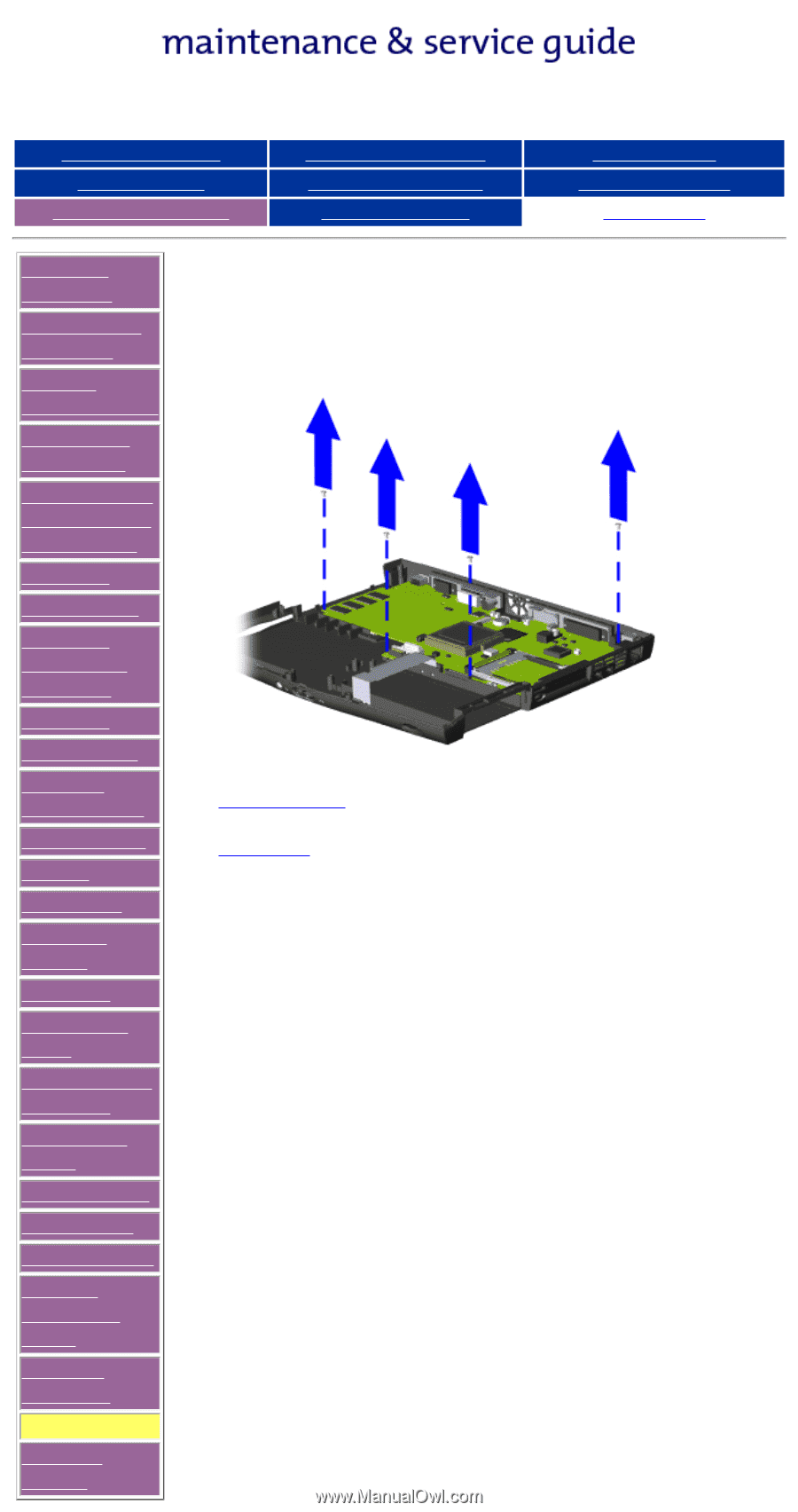
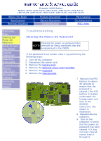
Presario 1600 Series Models: 1600T, 1600-XL140, 1600-XL141, 1600-XL142, 1600-XL143, 1600-XL144, 1600-XL145, 1600-XL146, 1600-XL147, and 1600-XL150 Before You Begin Specifications Removal Sequence Product Description Battery Operations Troubleshooting Parts Catalog Pin Assignments MSG Index Removal Sequence Electrostatic Discharge Service Considerations Cables and Connectors Preparing the Computer for Disassembly QuikDock Battery Pack Palmrest Cover with TouchPad Keyboard Status Panel Internet Button Board Heatspreader Modem Hard Drive DisqPlay Module Processor CD or DVD Drive Display Panel Assembly Upper CPU Cover Fan Assembly RTC Battery Diskette Drive Voltage Converter Board Speaker Assembly System Board Memory Module Removal Sequence Removing the System Board, continued 19. Remove four screws from the system board. Previous Step Next Step
-
 1
1 -
2
-
3
-
4
-
5
-
6
-
7
-
8
-
9
-
10
-
11
-
12
-
13
-
14
-
15
-
16
-
17
-
18
-
19
-
20
-
21
-
22
-
23
-
24
-
25
-
26
-
27
-
28
-
29
-
30
-
31
-
32
-
33
-
34
-
35
-
36
-
37
-
38
-
39
-
40
-
41
-
42
-
43
-
44
-
45
-
46
-
47
-
48
-
49
-
50
-
51
-
52
-
53
-
54
-
55
-
56
-
57
-
58
-
59
-
60
-
61
-
62
-
63
-
64
-
65
-
66
-
67
-
68
-
69
-
70
-
71
-
72
-
73
-
74
-
 75
75 -
 76
76 -
 77
77 -
 78
78 -
 79
79 -
 80
80 -
 81
81 -
 82
82 -
 83
83 -
 84
84 -
 85
85 -
86
-
87
-
88
-
89
-
90
-
91
-
92
 |
 |