HP Presario CQ43-300 Compaq Presario CQ43 Notebook PC Maintenance and Service - Page 76
Detach and release the module, If it is necessary to replace the webcam/microphone module
 |
View all HP Presario CQ43-300 manuals
Add to My Manuals
Save this manual to your list of manuals |
Page 76 highlights
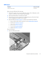
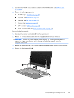
5. If it is necessary to replace the display bezel or any of the display assembly subcomponents: a. Remove the two Mylar screw covers (1) and the two Phillips PM2.5×4.0 screws (2) that secure the display bezel to the display assembly. The Mylar screw covers are available in the Display Screw Kit, spare part number 645976-001. b. Flex the inside edges of the top edge (1), the left and right sides (2), and the bottom edge (3) of the display bezel until the bezel disengages from the display enclosure. c. Remove the display bezel (4). The display bezel is available using spare part number 645964-001. 6. If it is necessary to replace the webcam/microphone module: a. Detach and release the module (1) as far as the module cable allows. (The module is attached to the display enclosure with double-sided tape.) b. Disconnect the module cable (2) from the module. 68 Chapter 4 Removal and replacement procedures
-
 1
1 -
2
-
3
-
4
-
5
-
6
-
7
-
8
-
9
-
10
-
11
-
12
-
13
-
14
-
15
-
16
-
17
-
18
-
19
-
20
-
21
-
22
-
23
-
24
-
25
-
26
-
27
-
28
-
29
-
30
-
31
-
32
-
33
-
34
-
35
-
36
-
37
-
38
-
39
-
40
-
41
-
42
-
43
-
44
-
45
-
46
-
47
-
48
-
49
-
50
-
51
-
52
-
53
-
54
-
55
-
56
-
57
-
58
-
59
-
60
-
61
-
62
-
63
-
64
-
65
-
66
-
67
-
68
-
69
-
70
-
 71
71 -
 72
72 -
 73
73 -
 74
74 -
 75
75 -
 76
76 -
 77
77 -
 78
78 -
 79
79 -
 80
80 -
 81
81 -
82
-
83
-
84
-
85
-
86
-
87
-
88
-
89
-
90
-
91
-
92
-
93
-
94
-
95
-
96
-
97
-
98
-
99
-
100
-
101
-
102
-
103
-
104
-
105
-
106
-
107
-
108
-
109
-
110
-
111
-
112
-
113
-
114
-
115
-
116
-
117
-
118
-
119
-
120
-
121
 |
 |
