HP Presario X1200 HP and Compaq Notebook PC Series - Maintenance and Service G - Page 102
a 45-degree angle., expansion board to the socket. The board rises up
 |
View all HP Presario X1200 manuals
Add to My Manuals
Save this manual to your list of manuals |
Page 102 highlights
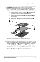
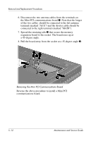
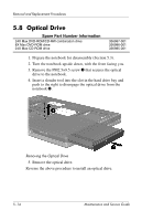
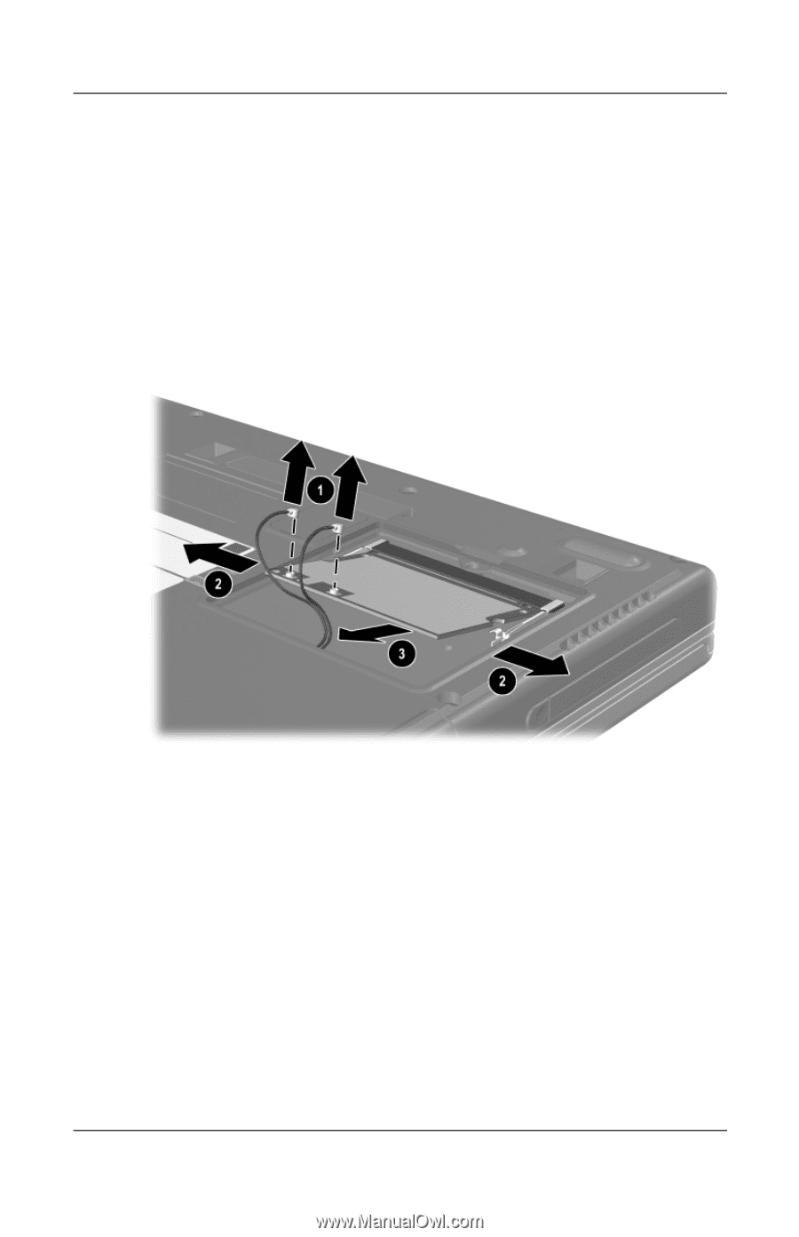
Removal and Replacement Procedures 6. Disconnect the two antenna cables from the terminals on the Mini PCI communications board 1. Note that the longer of the two cables should be connected to the left antenna terminal (marked "AUX") and the shorter cable should be connected to the right terminal (marked "MAIN"). 7. Spread the retaining tabs 2 that secure the memory expansion board to the socket. The board rises up at a 45-degree angle. 8. Pull the board away from the socket at a 45-degree angle 3. Removing the Mini PCI Communications Board Reverse the above procedure to install a Mini PCI communications board. 5-12 Maintenance and Service Guide
-
 1
1 -
2
-
3
-
4
-
5
-
6
-
7
-
8
-
9
-
10
-
11
-
12
-
13
-
14
-
15
-
16
-
17
-
18
-
19
-
20
-
21
-
22
-
23
-
24
-
25
-
26
-
27
-
28
-
29
-
30
-
31
-
32
-
33
-
34
-
35
-
36
-
37
-
38
-
39
-
40
-
41
-
42
-
43
-
44
-
45
-
46
-
47
-
48
-
49
-
50
-
51
-
52
-
53
-
54
-
55
-
56
-
57
-
58
-
59
-
60
-
61
-
62
-
63
-
64
-
65
-
66
-
67
-
68
-
69
-
70
-
71
-
72
-
73
-
74
-
75
-
76
-
77
-
78
-
79
-
80
-
81
-
82
-
83
-
84
-
85
-
86
-
87
-
88
-
89
-
90
-
91
-
92
-
93
-
94
-
95
-
96
-
 97
97 -
 98
98 -
 99
99 -
 100
100 -
 101
101 -
 102
102 -
 103
103 -
 104
104 -
 105
105 -
 106
106 -
 107
107 -
108
-
109
-
110
-
111
-
112
-
113
-
114
-
115
-
116
-
117
-
118
-
119
-
120
-
121
-
122
-
123
-
124
-
125
-
126
-
127
-
128
-
129
-
130
-
131
-
132
-
133
-
134
-
135
-
136
-
137
-
138
-
139
-
140
-
141
-
142
-
143
-
144
-
145
-
146
-
147
-
148
-
149
-
150
-
151
-
152
-
153
-
154
-
155
-
156
-
157
-
158
-
159
-
160
-
161
-
162
-
163
-
164
-
165
-
166
-
167
-
168
-
169
-
170
-
171
-
172
-
173
-
174
-
175
-
176
-
177
-
178
-
179
-
180
-
181
-
182
-
183
-
184
-
185
-
186
 |
 |
5–12
Maintenance and Service Guide
Removal and Replacement Procedures
6. Disconnect the two antenna cables from the terminals on
the Mini PCI communications board
1
. Note that the longer
of the two cables should be connected to the left antenna
terminal (marked “AUX”) and the shorter cable should be
connected to the right terminal (marked “MAIN”).
7. Spread the retaining tabs
2
that secure the memory
expansion board to the socket. The board rises up at
a 45-degree angle.
8. Pull the board away from the socket at a 45-degree angle
3
.
Removing the Mini PCI Communications Board
Reverse the above procedure to install a Mini PCI
communications board.