HP Presario X1200 HP and Compaq Notebook PC Series - Maintenance and Service G - Page 107
system board., Board for instructions on removing the internal memory
 |
View all HP Presario X1200 manuals
Add to My Manuals
Save this manual to your list of manuals |
Page 107 highlights
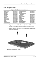
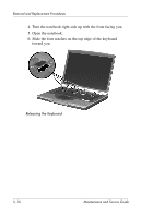
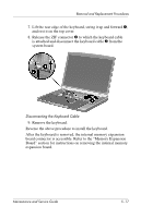
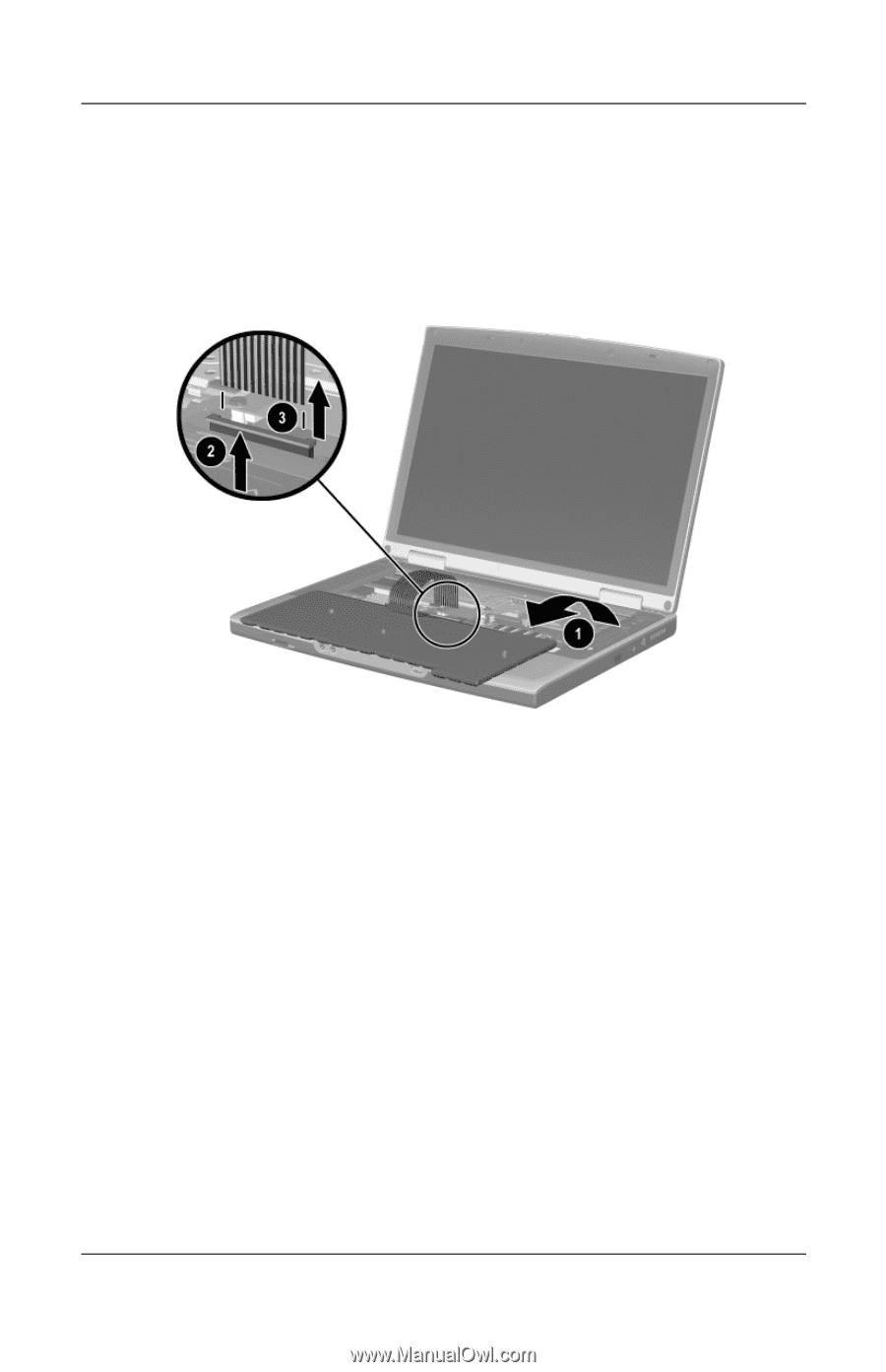
Removal and Replacement Procedures 7. Lift the rear edge of the keyboard, swing it up and forward 1, and rest it on the top cover. 8. Release the ZIF connector 2 to which the keyboard cable is attached and disconnect the keyboard cable 3 from the system board. Disconnecting the Keyboard Cable 9. Remove the keyboard. Reverse the above procedure to install the keyboard. After the keyboard is removed, the internal memory expansion board connector is accessible. Refer to the "Memory Expansion Board" section for instructions on removing the internal memory expansion board. Maintenance and Service Guide 5-17
-
 1
1 -
2
-
3
-
4
-
5
-
6
-
7
-
8
-
9
-
10
-
11
-
12
-
13
-
14
-
15
-
16
-
17
-
18
-
19
-
20
-
21
-
22
-
23
-
24
-
25
-
26
-
27
-
28
-
29
-
30
-
31
-
32
-
33
-
34
-
35
-
36
-
37
-
38
-
39
-
40
-
41
-
42
-
43
-
44
-
45
-
46
-
47
-
48
-
49
-
50
-
51
-
52
-
53
-
54
-
55
-
56
-
57
-
58
-
59
-
60
-
61
-
62
-
63
-
64
-
65
-
66
-
67
-
68
-
69
-
70
-
71
-
72
-
73
-
74
-
75
-
76
-
77
-
78
-
79
-
80
-
81
-
82
-
83
-
84
-
85
-
86
-
87
-
88
-
89
-
90
-
91
-
92
-
93
-
94
-
95
-
96
-
97
-
98
-
99
-
100
-
101
-
 102
102 -
 103
103 -
 104
104 -
 105
105 -
 106
106 -
 107
107 -
 108
108 -
 109
109 -
 110
110 -
 111
111 -
 112
112 -
113
-
114
-
115
-
116
-
117
-
118
-
119
-
120
-
121
-
122
-
123
-
124
-
125
-
126
-
127
-
128
-
129
-
130
-
131
-
132
-
133
-
134
-
135
-
136
-
137
-
138
-
139
-
140
-
141
-
142
-
143
-
144
-
145
-
146
-
147
-
148
-
149
-
150
-
151
-
152
-
153
-
154
-
155
-
156
-
157
-
158
-
159
-
160
-
161
-
162
-
163
-
164
-
165
-
166
-
167
-
168
-
169
-
170
-
171
-
172
-
173
-
174
-
175
-
176
-
177
-
178
-
179
-
180
-
181
-
182
-
183
-
184
-
185
-
186
 |
 |
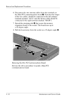
Removal and Replacement Procedures
Maintenance and Service Guide
5–17
7.
Lift the rear edge of the keyboard, swing it up and forward
1
,
and rest it on the top cover.
8. Release the ZIF connector
2
to which the keyboard cable
is attached and disconnect the keyboard cable
3
from the
system board.
Disconnecting the Keyboard Cable
9. Remove the keyboard.
Reverse the above procedure to install the keyboard.
After the keyboard is removed, the internal memory expansion
board connector is accessible. Refer to the “Memory Expansion
Board” section for instructions on removing the internal memory
expansion board.