HP Presario X1200 HP and Compaq Notebook PC Series - Maintenance and Service G - Page 136
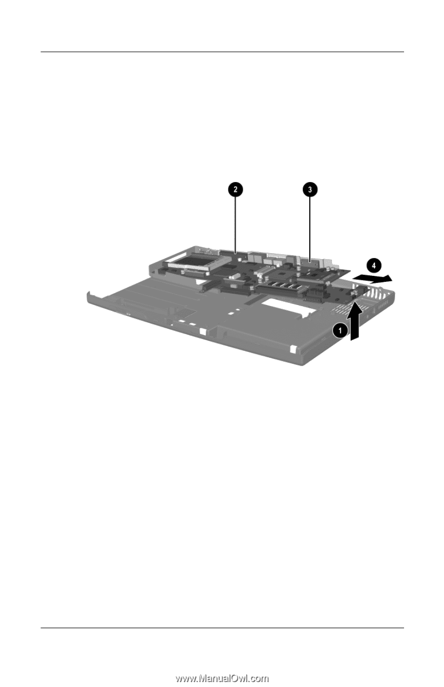
Slide the system board to the right at an angle, Remove the system board.
 |
View all HP Presario X1200 manuals
Add to My Manuals
Save this manual to your list of manuals |
Page 136 highlights
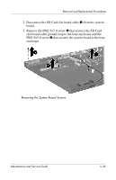
Removal and Replacement Procedures 4. Lift the right side of the system board approximately 1 inch 1. If necessary, flex the back edge of the base enclosure out so that the parallel 2 and serial connectors 3 clear the base enclosure. 5. Slide the system board to the right at an angle 4. 6. Remove the system board. Removing the System Board Reverse the above procedure to install the system board. 5-46 Maintenance and Service Guide
-
 1
1 -
2
-
3
-
4
-
5
-
6
-
7
-
8
-
9
-
10
-
11
-
12
-
13
-
14
-
15
-
16
-
17
-
18
-
19
-
20
-
21
-
22
-
23
-
24
-
25
-
26
-
27
-
28
-
29
-
30
-
31
-
32
-
33
-
34
-
35
-
36
-
37
-
38
-
39
-
40
-
41
-
42
-
43
-
44
-
45
-
46
-
47
-
48
-
49
-
50
-
51
-
52
-
53
-
54
-
55
-
56
-
57
-
58
-
59
-
60
-
61
-
62
-
63
-
64
-
65
-
66
-
67
-
68
-
69
-
70
-
71
-
72
-
73
-
74
-
75
-
76
-
77
-
78
-
79
-
80
-
81
-
82
-
83
-
84
-
85
-
86
-
87
-
88
-
89
-
90
-
91
-
92
-
93
-
94
-
95
-
96
-
97
-
98
-
99
-
100
-
101
-
102
-
103
-
104
-
105
-
106
-
107
-
108
-
109
-
110
-
111
-
112
-
113
-
114
-
115
-
116
-
117
-
118
-
119
-
120
-
121
-
122
-
123
-
124
-
125
-
126
-
127
-
128
-
129
-
130
-
 131
131 -
 132
132 -
 133
133 -
 134
134 -
 135
135 -
 136
136 -
 137
137 -
 138
138 -
 139
139 -
 140
140 -
 141
141 -
142
-
143
-
144
-
145
-
146
-
147
-
148
-
149
-
150
-
151
-
152
-
153
-
154
-
155
-
156
-
157
-
158
-
159
-
160
-
161
-
162
-
163
-
164
-
165
-
166
-
167
-
168
-
169
-
170
-
171
-
172
-
173
-
174
-
175
-
176
-
177
-
178
-
179
-
180
-
181
-
182
-
183
-
184
-
185
-
186
 |
 |
5–46
Maintenance and Service Guide
Removal and Replacement Procedures
4. Lift the right side of the system board approximately
1 inch
1
. If necessary, flex the back edge of the base
enclosure out so that the parallel
2
and serial connectors
3
clear the base enclosure.
5. Slide the system board to the right at an angle
4
.
6. Remove the system board.
Removing the System Board
Reverse the above procedure to install the system board.