HP Presario X1200 HP and Compaq Notebook PC Series - Maintenance and Service G - Page 133
Top cover
 |
View all HP Presario X1200 manuals
Add to My Manuals
Save this manual to your list of manuals |
Page 133 highlights
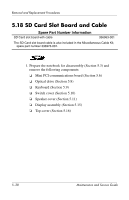
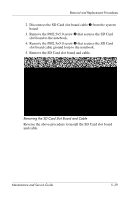
Removal and Replacement Procedures ❏ Speaker cover (Section 5.11) ❏ Display assembly (Section 5.15) ❏ Top cover (Section 5.16) ❏ VGA board and shield (Section 5.19) 2. Disconnect the modem cable 1 from the system board. 3. Lift the left side of the modem board 2 to disconnect it from the system board. 4. Remove the modem board. Removing the Modem Board and Cable Reverse the above procedure to install the modem and cable. Maintenance and Service Guide 5-43
-
 1
1 -
2
-
3
-
4
-
5
-
6
-
7
-
8
-
9
-
10
-
11
-
12
-
13
-
14
-
15
-
16
-
17
-
18
-
19
-
20
-
21
-
22
-
23
-
24
-
25
-
26
-
27
-
28
-
29
-
30
-
31
-
32
-
33
-
34
-
35
-
36
-
37
-
38
-
39
-
40
-
41
-
42
-
43
-
44
-
45
-
46
-
47
-
48
-
49
-
50
-
51
-
52
-
53
-
54
-
55
-
56
-
57
-
58
-
59
-
60
-
61
-
62
-
63
-
64
-
65
-
66
-
67
-
68
-
69
-
70
-
71
-
72
-
73
-
74
-
75
-
76
-
77
-
78
-
79
-
80
-
81
-
82
-
83
-
84
-
85
-
86
-
87
-
88
-
89
-
90
-
91
-
92
-
93
-
94
-
95
-
96
-
97
-
98
-
99
-
100
-
101
-
102
-
103
-
104
-
105
-
106
-
107
-
108
-
109
-
110
-
111
-
112
-
113
-
114
-
115
-
116
-
117
-
118
-
119
-
120
-
121
-
122
-
123
-
124
-
125
-
126
-
127
-
 128
128 -
 129
129 -
 130
130 -
 131
131 -
 132
132 -
 133
133 -
 134
134 -
 135
135 -
 136
136 -
 137
137 -
 138
138 -
139
-
140
-
141
-
142
-
143
-
144
-
145
-
146
-
147
-
148
-
149
-
150
-
151
-
152
-
153
-
154
-
155
-
156
-
157
-
158
-
159
-
160
-
161
-
162
-
163
-
164
-
165
-
166
-
167
-
168
-
169
-
170
-
171
-
172
-
173
-
174
-
175
-
176
-
177
-
178
-
179
-
180
-
181
-
182
-
183
-
184
-
185
-
186
 |
 |
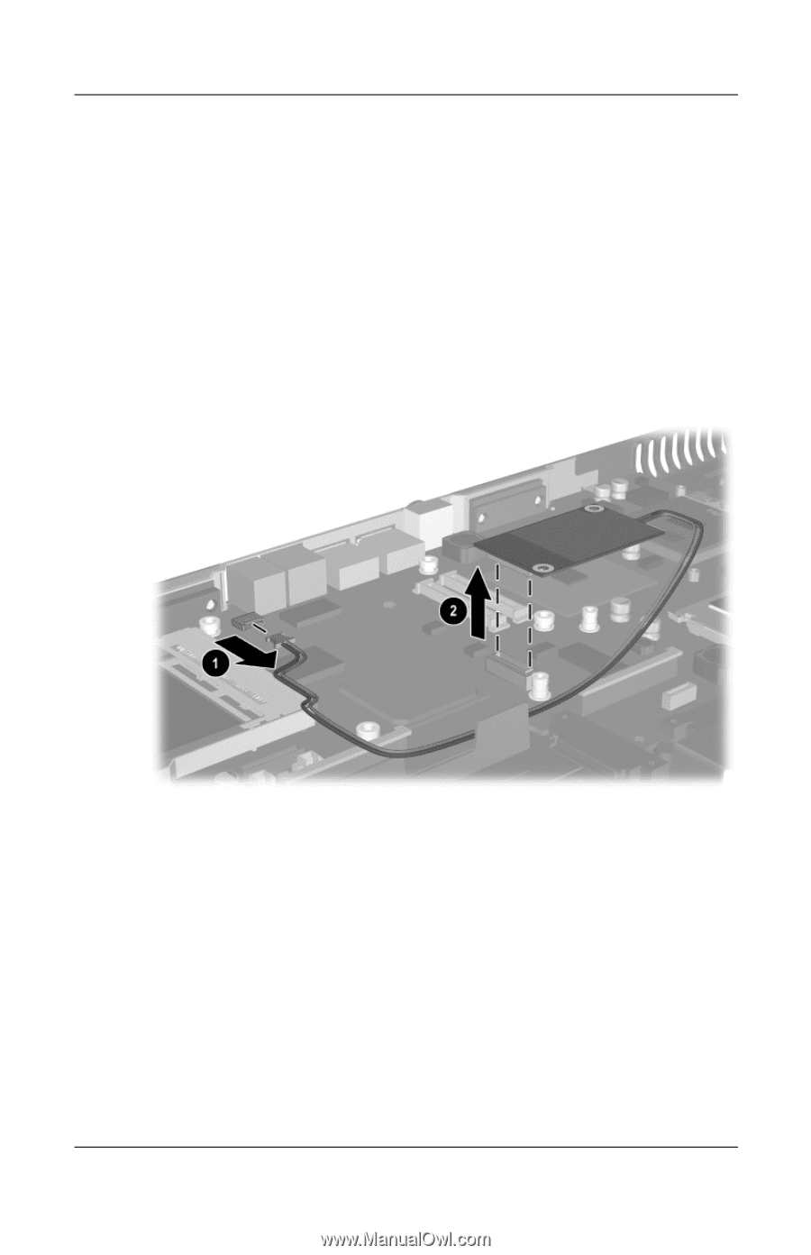
Removal and Replacement Procedures
Maintenance and Service Guide
5–43
❏
Speaker cover (Section 5.11)
❏
Display assembly (Section 5.15)
❏
Top cover (Section 5.16)
❏
VGA board and shield (Section 5.19)
2. Disconnect the modem cable
1
from the system board.
3. Lift the left side of the modem board
2
to disconnect it from
the system board.
4. Remove the modem board.
Removing the Modem Board and Cable
Reverse the above procedure to install the modem and cable.