HP Presario X1200 HP and Compaq Notebook PC Series - Maintenance and Service G - Page 132
Modem and Cable
 |
View all HP Presario X1200 manuals
Add to My Manuals
Save this manual to your list of manuals |
Page 132 highlights
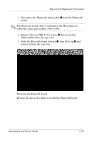
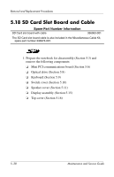
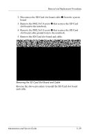
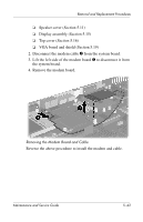
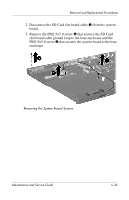
Removal and Replacement Procedures 6. The VGA shield thermal pad 1 and VGA board thermal pad 2 assist in cooling the notebook. Inspect these pads and replace if necessary each time the shield is removed. Replacing the Thermal Pads on the VGA Board and Shield Reverse the above procedure to install the VGA board and shield. 5.20 Modem and Cable Spare Part Number Information Modem board with cable 336999-001 The modem board cable is also included in the Miscellaneous Cable Kit, spare part number 3361973-001. 1. Prepare the notebook for disassembly (Section 5.3) and remove the following components: ❏ Mini PCI communications board (Section 5.6) ❏ Optical drive (Section 5.8) ❏ Keyboard (Section 5.9) ❏ Switch cover (Section 5.10) 5-42 Maintenance and Service Guide
-
 1
1 -
2
-
3
-
4
-
5
-
6
-
7
-
8
-
9
-
10
-
11
-
12
-
13
-
14
-
15
-
16
-
17
-
18
-
19
-
20
-
21
-
22
-
23
-
24
-
25
-
26
-
27
-
28
-
29
-
30
-
31
-
32
-
33
-
34
-
35
-
36
-
37
-
38
-
39
-
40
-
41
-
42
-
43
-
44
-
45
-
46
-
47
-
48
-
49
-
50
-
51
-
52
-
53
-
54
-
55
-
56
-
57
-
58
-
59
-
60
-
61
-
62
-
63
-
64
-
65
-
66
-
67
-
68
-
69
-
70
-
71
-
72
-
73
-
74
-
75
-
76
-
77
-
78
-
79
-
80
-
81
-
82
-
83
-
84
-
85
-
86
-
87
-
88
-
89
-
90
-
91
-
92
-
93
-
94
-
95
-
96
-
97
-
98
-
99
-
100
-
101
-
102
-
103
-
104
-
105
-
106
-
107
-
108
-
109
-
110
-
111
-
112
-
113
-
114
-
115
-
116
-
117
-
118
-
119
-
120
-
121
-
122
-
123
-
124
-
125
-
126
-
 127
127 -
 128
128 -
 129
129 -
 130
130 -
 131
131 -
 132
132 -
 133
133 -
 134
134 -
 135
135 -
 136
136 -
 137
137 -
138
-
139
-
140
-
141
-
142
-
143
-
144
-
145
-
146
-
147
-
148
-
149
-
150
-
151
-
152
-
153
-
154
-
155
-
156
-
157
-
158
-
159
-
160
-
161
-
162
-
163
-
164
-
165
-
166
-
167
-
168
-
169
-
170
-
171
-
172
-
173
-
174
-
175
-
176
-
177
-
178
-
179
-
180
-
181
-
182
-
183
-
184
-
185
-
186
 |
 |