HP Presario X1200 HP and Compaq Notebook PC Series - Maintenance and Service G - Page 93
Disassembly Sequence Chart, Use the following chart to determine the number to
 |
View all HP Presario X1200 manuals
Add to My Manuals
Save this manual to your list of manuals |
Page 93 highlights
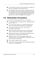
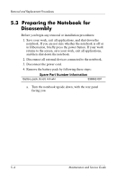
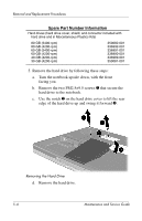
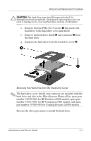
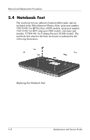
Removal and Replacement Procedures 5.2 Disassembly Sequence Chart Use the following chart to determine the section number to be referenced when removing notebook components. Disassembly Sequence Chart Section Description # of Screws Removed 5.3 Preparing the notebook for disassembly Battery pack 0 Hard drive 2 Hard drive cover and shield 4 5.4 Notebook feet 0 5.5 Memory expansion board 1 5.6 Mini PCI communications board 1 5.7 RTC battery 0 5.8 Optical drive 1 5.9 Keyboard 2 5.10 Switch cover 0 5.11 Speaker cover 4 5.12 Fan 1 5.13 Heat sink 4 5.14 Processor 0 5.15 Display assembly 7 5.16 Top cover 16 5.17 Bluetooth board 2 5.18 SD Card slot board and cable 2 5.19 VGA board and shield 2 5.20 Modem board and cable 0 5.21 System board 1 Maintenance and Service Guide 5-3
-
 1
1 -
2
-
3
-
4
-
5
-
6
-
7
-
8
-
9
-
10
-
11
-
12
-
13
-
14
-
15
-
16
-
17
-
18
-
19
-
20
-
21
-
22
-
23
-
24
-
25
-
26
-
27
-
28
-
29
-
30
-
31
-
32
-
33
-
34
-
35
-
36
-
37
-
38
-
39
-
40
-
41
-
42
-
43
-
44
-
45
-
46
-
47
-
48
-
49
-
50
-
51
-
52
-
53
-
54
-
55
-
56
-
57
-
58
-
59
-
60
-
61
-
62
-
63
-
64
-
65
-
66
-
67
-
68
-
69
-
70
-
71
-
72
-
73
-
74
-
75
-
76
-
77
-
78
-
79
-
80
-
81
-
82
-
83
-
84
-
85
-
86
-
87
-
 88
88 -
 89
89 -
 90
90 -
 91
91 -
 92
92 -
 93
93 -
 94
94 -
 95
95 -
 96
96 -
 97
97 -
 98
98 -
99
-
100
-
101
-
102
-
103
-
104
-
105
-
106
-
107
-
108
-
109
-
110
-
111
-
112
-
113
-
114
-
115
-
116
-
117
-
118
-
119
-
120
-
121
-
122
-
123
-
124
-
125
-
126
-
127
-
128
-
129
-
130
-
131
-
132
-
133
-
134
-
135
-
136
-
137
-
138
-
139
-
140
-
141
-
142
-
143
-
144
-
145
-
146
-
147
-
148
-
149
-
150
-
151
-
152
-
153
-
154
-
155
-
156
-
157
-
158
-
159
-
160
-
161
-
162
-
163
-
164
-
165
-
166
-
167
-
168
-
169
-
170
-
171
-
172
-
173
-
174
-
175
-
176
-
177
-
178
-
179
-
180
-
181
-
182
-
183
-
184
-
185
-
186
 |
 |