HP ProBook 4325s HP ProBook 4325s, 4326s and 4425s Notebook PCs - Maintenance - Page 81
system board
 |
View all HP ProBook 4325s manuals
Add to My Manuals
Save this manual to your list of manuals |
Page 81 highlights
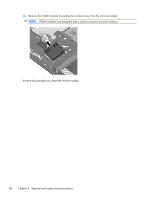
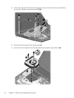
7. Following the sequence stamped into the heat sink, loosen the four PM2.5×10.0 captive screws (1) that secure the heat sink to the processor. NOTE: Loosen the two additional screws that secure the heat sink to the graphics devices on models with discrete graphics subsystem memory. 8. Lift the heat sink off the processor (2), and then lift the heat sink up and to the right to remove the heat sink from the base enclosure (3). NOTE: The thermal material must be thoroughly cleaned from the surfaces heat sink for the discrete system board (1), (2), and (3), and the system board (4), (5), and (6) each time the heat sink is removed. Replacement thermal material is included with all heat sink, system board, and processor spare part kits. Component replacement procedures 73
-
 1
1 -
2
-
3
-
4
-
5
-
6
-
7
-
8
-
9
-
10
-
11
-
12
-
13
-
14
-
15
-
16
-
17
-
18
-
19
-
20
-
21
-
22
-
23
-
24
-
25
-
26
-
27
-
28
-
29
-
30
-
31
-
32
-
33
-
34
-
35
-
36
-
37
-
38
-
39
-
40
-
41
-
42
-
43
-
44
-
45
-
46
-
47
-
48
-
49
-
50
-
51
-
52
-
53
-
54
-
55
-
56
-
57
-
58
-
59
-
60
-
61
-
62
-
63
-
64
-
65
-
66
-
67
-
68
-
69
-
70
-
71
-
72
-
73
-
74
-
75
-
 76
76 -
 77
77 -
 78
78 -
 79
79 -
 80
80 -
 81
81 -
 82
82 -
 83
83 -
 84
84 -
 85
85 -
 86
86 -
87
-
88
-
89
-
90
-
91
-
92
-
93
-
94
-
95
-
96
-
97
-
98
-
99
-
100
-
101
-
102
-
103
-
104
-
105
-
106
-
107
-
108
-
109
-
110
-
111
-
112
-
113
-
114
-
115
-
116
-
117
-
118
-
119
-
120
-
121
-
122
-
123
-
124
-
125
-
126
-
127
-
128
-
129
-
130
-
131
-
132
-
133
-
134
-
135
-
136
-
137
-
138
-
139
-
140
-
141
-
142
-
143
-
144
-
145
-
146
-
147
-
148
-
149
-
150
-
151
-
152
-
153
-
154
-
155
-
156
-
157
-
158
-
159
-
160
-
161
-
162
 |
 |
