HP ProBook 4325s HP ProBook 4325s, 4326s and 4425s Notebook PCs - Maintenance - Page 89
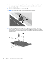
Flex the bottom of the bezel from the inside edge until it disengages from the display back
 |
View all HP ProBook 4325s manuals
Add to My Manuals
Save this manual to your list of manuals |
Page 89 highlights
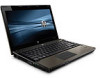
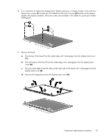
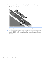
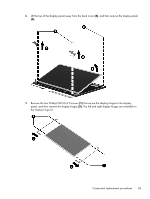
4. If it is necessary to replace the display bezel, display enclosure, or display hinges, remove the four Mylar screw covers (1) and the four T8 slotted-Torx M2.5×6.0 screws (2) that secure the display bezel to the display assembly. The screw covers are available in the rubber kit, spare part number 599564-001. 5. Remove the bezel: a. Flex the top of the bezel from the inside edge until it disengages from the display back cover (1). b. Flex the bottom of the bezel from the inside edge until it disengages from the display back cover (2). c. Flex the inside edge of the left side and the right side of the bezel until it disengages from the display back cover (3). d. Remove the display bezel from the display back cover (4). Component replacement procedures 81
-
 1
1 -
2
-
3
-
4
-
5
-
6
-
7
-
8
-
9
-
10
-
11
-
12
-
13
-
14
-
15
-
16
-
17
-
18
-
19
-
20
-
21
-
22
-
23
-
24
-
25
-
26
-
27
-
28
-
29
-
30
-
31
-
32
-
33
-
34
-
35
-
36
-
37
-
38
-
39
-
40
-
41
-
42
-
43
-
44
-
45
-
46
-
47
-
48
-
49
-
50
-
51
-
52
-
53
-
54
-
55
-
56
-
57
-
58
-
59
-
60
-
61
-
62
-
63
-
64
-
65
-
66
-
67
-
68
-
69
-
70
-
71
-
72
-
73
-
74
-
75
-
76
-
77
-
78
-
79
-
80
-
81
-
82
-
83
-
 84
84 -
 85
85 -
 86
86 -
 87
87 -
 88
88 -
 89
89 -
 90
90 -
 91
91 -
 92
92 -
 93
93 -
 94
94 -
95
-
96
-
97
-
98
-
99
-
100
-
101
-
102
-
103
-
104
-
105
-
106
-
107
-
108
-
109
-
110
-
111
-
112
-
113
-
114
-
115
-
116
-
117
-
118
-
119
-
120
-
121
-
122
-
123
-
124
-
125
-
126
-
127
-
128
-
129
-
130
-
131
-
132
-
133
-
134
-
135
-
136
-
137
-
138
-
139
-
140
-
141
-
142
-
143
-
144
-
145
-
146
-
147
-
148
-
149
-
150
-
151
-
152
-
153
-
154
-
155
-
156
-
157
-
158
-
159
-
160
-
161
-
162
 |
 |
