HP ProBook 4325s HP ProBook 4325s, 4326s and 4425s Notebook PCs - Maintenance - Page 99
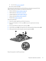
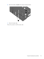
Position the computer right-side up with the front toward you.
 |
View all HP ProBook 4325s manuals
Add to My Manuals
Save this manual to your list of manuals |
Page 99 highlights
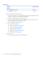
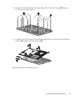
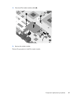
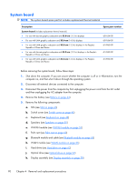
l. Top cover (see Top cover on page 86) m. Power connector and cable When replacing the system board, be sure that the following components are removed from the defective system board and installed on the replacement system board: ● Memory module (see Memory module on page 50) ● WLAN module (see WLAN module on page 66) ● WWAN module (see WWAN module on page 57) ● Modem module (see Modem module on page 88) ● Processor (see Processor on page 75) Remove the system board: 1. Position the computer right-side up with the front toward you. 2. Remove the T8 slotted-Torx 2.5×5.0 screw (1) that secures the system board to the base enclosure. 3. Disconnect the USB board cable from the system board (2). 4. Use the ODD connector (3) to lift the right side of the system board from the base enclosure (4). 5. Lift the system board up and to the right to remove the system board (5). Reverse this procedure to install the system board. Component replacement procedures 91
-
 1
1 -
2
-
3
-
4
-
5
-
6
-
7
-
8
-
9
-
10
-
11
-
12
-
13
-
14
-
15
-
16
-
17
-
18
-
19
-
20
-
21
-
22
-
23
-
24
-
25
-
26
-
27
-
28
-
29
-
30
-
31
-
32
-
33
-
34
-
35
-
36
-
37
-
38
-
39
-
40
-
41
-
42
-
43
-
44
-
45
-
46
-
47
-
48
-
49
-
50
-
51
-
52
-
53
-
54
-
55
-
56
-
57
-
58
-
59
-
60
-
61
-
62
-
63
-
64
-
65
-
66
-
67
-
68
-
69
-
70
-
71
-
72
-
73
-
74
-
75
-
76
-
77
-
78
-
79
-
80
-
81
-
82
-
83
-
84
-
85
-
86
-
87
-
88
-
89
-
90
-
91
-
92
-
93
-
 94
94 -
 95
95 -
 96
96 -
 97
97 -
 98
98 -
 99
99 -
 100
100 -
 101
101 -
 102
102 -
 103
103 -
 104
104 -
105
-
106
-
107
-
108
-
109
-
110
-
111
-
112
-
113
-
114
-
115
-
116
-
117
-
118
-
119
-
120
-
121
-
122
-
123
-
124
-
125
-
126
-
127
-
128
-
129
-
130
-
131
-
132
-
133
-
134
-
135
-
136
-
137
-
138
-
139
-
140
-
141
-
142
-
143
-
144
-
145
-
146
-
147
-
148
-
149
-
150
-
151
-
152
-
153
-
154
-
155
-
156
-
157
-
158
-
159
-
160
-
161
-
162
 |
 |
