HP ProBook 4325s HP ProBook 4325s, 4326s and 4425s Notebook PCs - Maintenance - Page 95
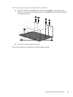
and then remove the top cover, Reverse this procedure to install the top cover.
 |
View all HP ProBook 4325s manuals
Add to My Manuals
Save this manual to your list of manuals |
Page 95 highlights
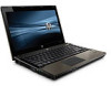
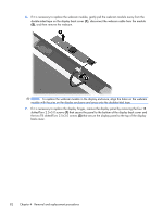
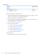
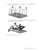
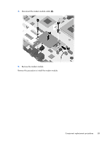
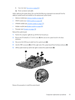
2. Remove the 14 T8 slotted-Torx 2.5×5.0 screws (1) and the 3 PM2.0×3.0 screws (2) that secure the top cover to the base enclosure. 3. If installed, remove the ExpressCard slot bezel (1), release the top cover from the sides of the base enclosure (2), and then remove the top cover (3). Reverse this procedure to install the top cover. Component replacement procedures 87
-
 1
1 -
2
-
3
-
4
-
5
-
6
-
7
-
8
-
9
-
10
-
11
-
12
-
13
-
14
-
15
-
16
-
17
-
18
-
19
-
20
-
21
-
22
-
23
-
24
-
25
-
26
-
27
-
28
-
29
-
30
-
31
-
32
-
33
-
34
-
35
-
36
-
37
-
38
-
39
-
40
-
41
-
42
-
43
-
44
-
45
-
46
-
47
-
48
-
49
-
50
-
51
-
52
-
53
-
54
-
55
-
56
-
57
-
58
-
59
-
60
-
61
-
62
-
63
-
64
-
65
-
66
-
67
-
68
-
69
-
70
-
71
-
72
-
73
-
74
-
75
-
76
-
77
-
78
-
79
-
80
-
81
-
82
-
83
-
84
-
85
-
86
-
87
-
88
-
89
-
 90
90 -
 91
91 -
 92
92 -
 93
93 -
 94
94 -
 95
95 -
 96
96 -
 97
97 -
 98
98 -
 99
99 -
 100
100 -
101
-
102
-
103
-
104
-
105
-
106
-
107
-
108
-
109
-
110
-
111
-
112
-
113
-
114
-
115
-
116
-
117
-
118
-
119
-
120
-
121
-
122
-
123
-
124
-
125
-
126
-
127
-
128
-
129
-
130
-
131
-
132
-
133
-
134
-
135
-
136
-
137
-
138
-
139
-
140
-
141
-
142
-
143
-
144
-
145
-
146
-
147
-
148
-
149
-
150
-
151
-
152
-
153
-
154
-
155
-
156
-
157
-
158
-
159
-
160
-
161
-
162
 |
 |

2.
Remove the 14 T8 slotted-Torx 2.5×5.0 screws
(1)
and the 3 PM2.0×3.0 screws
(2)
that secure
the top cover to the base enclosure.
3.
If installed, remove the ExpressCard slot bezel
(1)
, release the top cover from the sides of the base
enclosure
(2)
, and then remove the top cover
(3)
.
Reverse this procedure to install the top cover.
Component replacement procedures
87