HP ProBook 4325s HP ProBook 4325s, 4326s and 4425s Notebook PCs - Maintenance - Page 88
CAUTION, and remove all cables from the routing
 |
View all HP ProBook 4325s manuals
Add to My Manuals
Save this manual to your list of manuals |
Page 88 highlights
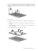
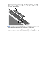
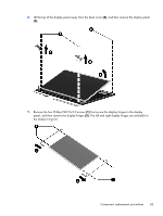
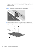
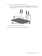
CAUTION: Support the display assembly when removing the following screws. Failure to support the display assembly can result in damage to the display assembly and other computer components. 1. Remove the five T8 slotted-Torx M2.5×6.0 screws (1) that secure the display assembly to the base enclosure. NOTE: Your model of the computer have four screws. 2. Disconnect the display cable from the system board (2), and remove all cables from the routing channels along the top cover (3). 3. Lift the display assembly (4) straight up and remove it from the base enclosure. 80 Chapter 4 Removal and replacement procedures
-
 1
1 -
2
-
3
-
4
-
5
-
6
-
7
-
8
-
9
-
10
-
11
-
12
-
13
-
14
-
15
-
16
-
17
-
18
-
19
-
20
-
21
-
22
-
23
-
24
-
25
-
26
-
27
-
28
-
29
-
30
-
31
-
32
-
33
-
34
-
35
-
36
-
37
-
38
-
39
-
40
-
41
-
42
-
43
-
44
-
45
-
46
-
47
-
48
-
49
-
50
-
51
-
52
-
53
-
54
-
55
-
56
-
57
-
58
-
59
-
60
-
61
-
62
-
63
-
64
-
65
-
66
-
67
-
68
-
69
-
70
-
71
-
72
-
73
-
74
-
75
-
76
-
77
-
78
-
79
-
80
-
81
-
82
-
 83
83 -
 84
84 -
 85
85 -
 86
86 -
 87
87 -
 88
88 -
 89
89 -
 90
90 -
 91
91 -
 92
92 -
 93
93 -
94
-
95
-
96
-
97
-
98
-
99
-
100
-
101
-
102
-
103
-
104
-
105
-
106
-
107
-
108
-
109
-
110
-
111
-
112
-
113
-
114
-
115
-
116
-
117
-
118
-
119
-
120
-
121
-
122
-
123
-
124
-
125
-
126
-
127
-
128
-
129
-
130
-
131
-
132
-
133
-
134
-
135
-
136
-
137
-
138
-
139
-
140
-
141
-
142
-
143
-
144
-
145
-
146
-
147
-
148
-
149
-
150
-
151
-
152
-
153
-
154
-
155
-
156
-
157
-
158
-
159
-
160
-
161
-
162
 |
 |

CAUTION:
Support the display assembly when removing the following screws. Failure to support the
display assembly can result in damage to the display assembly and other computer components.
1.
Remove the five T8 slotted-Torx M2.5×6.0 screws
(1)
that secure the display assembly to the base
enclosure.
NOTE:
Your model of the computer have four screws.
2.
Disconnect the display cable from the system board
(2)
, and remove all cables from the routing
channels along the top cover
(3)
.
3.
Lift the display assembly
(4)
straight up and remove it from the base enclosure.
80
Chapter 4
Removal and replacement procedures