HP R1500 HP UPS R3000 User Guide - Page 28
Con mode, Auto-Bypass mode, Configuring the UPS
 |
View all HP R1500 manuals
Add to My Manuals
Save this manual to your list of manuals |
Page 28 highlights
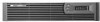
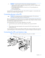
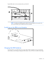
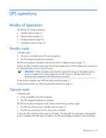
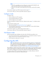
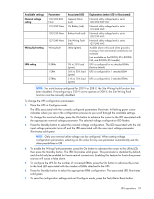
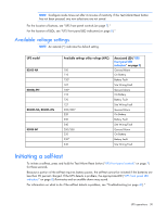
NOTE: • If the UPS is using battery power (no utility power is present and the Utility LED is red), press and hold the On button until the audible alarm sounds. • If the UPS is off (no LEDs are illuminated), press the On button to start the UPS on battery power. For the location of buttons, see "UPS front panel controls (on page 7)." For the location of LEDs, see "UPS front panel LED indicators (on page 8)." Configure mode In Configure mode: • Power is available at the UPS receptacles. • The UPS charges the batteries as necessary. • The UPS configuration can be updated. The UPS can be placed in Configure mode while in Operate mode (on page 27) or Standby mode (on page 27). To place the UPS in Configure mode: 1. Remove the front bezel ("Removing the UPS front bezel" on page 33). 2. Press and hold the Configure button until the front panel LEDs flash in unison and the Configure Mode On LED illuminates solid green. For the location of buttons, see "UPS front panel controls (on page 7)." For the location of LEDs, see "UPS front panel LED indicators (on page 8)." Auto-Bypass mode The UPS automatically enters Auto-Bypass mode when either of the following conditions occurs: • The power from the UPS reaches a percentage greater than 110 percent for more than 10 cycles or between 103 percent and 110 percent for more than 2 minutes. • The UPS electronics module fails or is removed. Configuring the UPS NOTE: If the UPS firmware version is 2.00 or later, follow the instructions in "Configuring the UPS." If the UPS firmware version is earlier than 2.00, or the ERM cannot be configured from the UPS front panel, use the ERM configurator tool. To update the UPS firmware or download the ERM configurator tool, see the HP website (http://www.hp.com/go/rackandpower). After the ERMs are installed, place the UPS in Configure mode (on page 28), and use the UPS front panel controls and LED indicators to configure the UPS for the number of attached ERMs. Other UPS parameters that can also be configured are the nominal utility voltage level and Site Wiring Fault detection. In Configure mode, the LED front panel display changes function to enable modification of the UPS parameters. Each LED is associated with a different parameter. UPS operations 28
-
 1
1 -
2
-
3
-
4
-
5
-
6
-
7
-
8
-
9
-
10
-
11
-
12
-
13
-
14
-
15
-
16
-
17
-
18
-
19
-
20
-
21
-
22
-
 23
23 -
 24
24 -
 25
25 -
 26
26 -
 27
27 -
 28
28 -
 29
29 -
 30
30 -
 31
31 -
 32
32 -
 33
33 -
34
-
35
-
36
-
37
-
38
-
39
-
40
-
41
-
42
-
43
-
44
-
45
-
46
-
47
-
48
-
49
-
50
-
51
-
52
-
53
-
54
-
55
-
56
-
57
-
58
-
59
-
60
-
61
-
62
-
63
-
64
-
65
 |
 |