HP R1500 HP UPS R3000 User Guide - Page 34
Replacing the UPS option card
 |
View all HP R1500 manuals
Add to My Manuals
Save this manual to your list of manuals |
Page 34 highlights
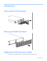
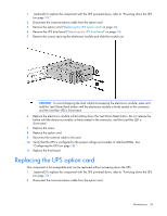
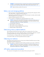
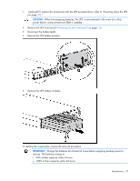
1. (optional) To replace the component with the UPS powered down, refer to "Powering down the UPS (on page 31)." 2. Disconnect the communications cable from the option card. 3. Remove the option card ("Replacing the UPS option card" on page 34). 4. Remove the UPS front bezel ("Removing the UPS front bezel" on page 33). 5. Remove the screws securing the electronics module and slide the module out. CAUTION: To avoid dropping the load while hot-swapping the electronics module, press and hold the Test/Alarm Reset button until the electronics module is firmly seated in the connector, and the Load Bar LED is illuminated. 6. Replace the electronics module while holding down the Test/Alarm Reset button. Do not release the button until the electronics module is firmly seated in the connector, and the Load Bar LED is illuminated. 7. Replace the screw. 8. Replace the option card. 9. Reconnect the external cable to the card. 10. Verify that the UPS is configured to the proper voltage and number of attached ERMs. See "Configuring the UPS (on page 28)." 11. Replace the front bezel. Replacing the UPS option card This component is hot-swappable and can be replaced without powering down the UPS. 1. (optional) To replace the component with the UPS powered down, refer to "Powering down the UPS (on page 31)." 2. Disconnect the communications cable from the option card. Maintenance 34
-
 1
1 -
2
-
3
-
4
-
5
-
6
-
7
-
8
-
9
-
10
-
11
-
12
-
13
-
14
-
15
-
16
-
17
-
18
-
19
-
20
-
21
-
22
-
23
-
24
-
25
-
26
-
27
-
28
-
 29
29 -
 30
30 -
 31
31 -
 32
32 -
 33
33 -
 34
34 -
 35
35 -
 36
36 -
 37
37 -
 38
38 -
 39
39 -
40
-
41
-
42
-
43
-
44
-
45
-
46
-
47
-
48
-
49
-
50
-
51
-
52
-
53
-
54
-
55
-
56
-
57
-
58
-
59
-
60
-
61
-
62
-
63
-
64
-
65
 |
 |
