HP R1500 HP UPS R3000 User Guide - Page 29
Available settings, Parameter, Associated LED, Explanation when LED is illuminated
 |
View all HP R1500 manuals
Add to My Manuals
Save this manual to your list of manuals |
Page 29 highlights
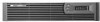
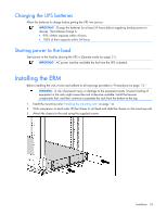
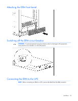
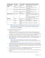
Available settings Nominal voltage setting Wiring fault setting ERM setting Parameter 100/200-208 Nom 110/220 Nom 120/230 Nom 127/240 Nom Wiring fault 0 ERMs 1 ERM 2 ERMs Associated LED General Alarm (red) On Battery (red) Battery Fault (red) Site Wiring Fault (red) Utility (green) 0% to 25% load (green) 26% to 50% load (green) 51% to 75% load (green) Explanation (when LED is illuminated) Nominal utility voltage level is set to 100/200-208 VAC Nominal utility voltage level is set to 110/220 VAC Nominal utility voltage level is set to 120/230 VAC Nominal utility voltage level is set to 127/240 VAC Audible alarm will sound when ground is missing or line and neutral connections are reversed (not available on the R3000j JPN, R3000h NA, and R3000h JPN models) UPS is configured for no attached ERMs (factory default) UPS is configured for 1 attached ERM UPS is configured for 2 attached ERMs NOTE: For units factory-configured for 200 V or 208 V, the Site Wiring Fault function has been disabled. If reconfiguring a 230 V unit to operate at 208 V, the Site Wiring Fault function must be manually disabled. To change the UPS configuration parameters: 1. Place the UPS in Configure mode. The LEDs associated with the currently configured parameters illuminate. A flashing green cursor indicates where you are in the configuration process as you scroll through the available settings. 2. To change the nominal voltage, press the On button to advance the cursor to the LED associated with the appropriate nominal voltage parameter. The selected voltage configuration LED flashes. 3. Press the Standby button to select the nominal voltage configuration. The LED associated with the old input voltage parameter turns off and the LED associated with the new input voltage parameter illuminates solid green. NOTE: Only one nominal utility voltage can be configured. When setting voltage configuration parameters, selecting an On value for any one parameter automatically sets the other possibilities to Off. 4. To enable the Wiring Fault parameter, press the On button to advance the cursor to the Utility LED, then press the Standby button. The LED illuminates solid green. This parameter is disabled by default, and should only be enabled for line-to-neutral connections. Enabling this feature for line-to-line power sources will cause a false alarm. 5. To configure the UPS for the number of connected ERMs, press the On button to advance the cursor to the load LED associated with the number of ERMs attached to the UPS. 6. Press the Standby button to select the appropriate ERM configuration. The associated LED illuminates solid green. 7. To save the configuration settings and exit Configure mode, press the Test/Alarm Reset button. UPS operations 29
-
 1
1 -
2
-
3
-
4
-
5
-
6
-
7
-
8
-
9
-
10
-
11
-
12
-
13
-
14
-
15
-
16
-
17
-
18
-
19
-
20
-
21
-
22
-
23
-
 24
24 -
 25
25 -
 26
26 -
 27
27 -
 28
28 -
 29
29 -
 30
30 -
 31
31 -
 32
32 -
 33
33 -
 34
34 -
35
-
36
-
37
-
38
-
39
-
40
-
41
-
42
-
43
-
44
-
45
-
46
-
47
-
48
-
49
-
50
-
51
-
52
-
53
-
54
-
55
-
56
-
57
-
58
-
59
-
60
-
61
-
62
-
63
-
64
-
65
 |
 |
