HP RP36000/3 HP 3 Phase UPS User Guide - Page 11
HD-384-48 S1, Electrical Installation of the Buildings, Part 4: Protection for Safety,
 |
View all HP RP36000/3 manuals
Add to My Manuals
Save this manual to your list of manuals |
Page 11 highlights
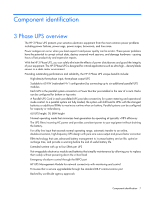
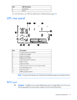
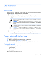
CAUTION: • Do not connect the REPO port to any utility connected circuits. Reinforced insulation to the utility is required. The REPO switch must have a minimum rating of 24 Vdc and 20 mA and be a dedicated latching-type switch for the 3 Phase UPS only, no other device or circuit including a single phase UPS. The REPO signal must remain active for at least 250 ms for proper operation. • To ensure that the UPS stops supplying power to the load during any mode of operation, the input power must be disconnected from the UPS when the EPO function is activated. NOTE: For Europe, the emergency switch requirements are detailed in Harmonized document HD-384-48 S1, "Electrical Installation of the Buildings, Part 4: Protection for Safety, Chapter 46: Isolation and Switching." The UPS includes an isolated REPO port. When properly wired, the REPO feature allows the power at the UPS output receptacles to be switched off from a remote location. When REPO is activated, the UPS powers down all converters, de-energizes all system relays, trips the UPS battery circuit breaker, and powers down within 10 to 15 seconds. However, the unit continues to have logic power (the display is still active) and is not fully powered down until input power is disconnected from the unit. This feature can be used for powering down the load and the UPS by thermal relay, for example in the event of room overtemperature. To use this feature, the REPO port must be connected to a remote switch (not supplied). The REPO switch is used in conjunction with a main disconnect device that removes the AC source from the input of the UPS. When the switch is activated: • The REPO feature immediately powers down protected devices and does not utilize the orderly shutdown procedure initiated by power management software. • The REPO feature shuts down UPS units operating under either utility or battery power. Keep the REPO connector installed in the REPO port on the UPS even if the REPO function is not needed. The REPO connection are listed below: Wire function L1 L2 Terminal wire size rating 4-0.32 mm2 (12-22 AWG) 4-0.32 mm2 (12-22 AWG) Suggested wire size 0.82 mm2 (18 AWG) 0.82 mm2 (18 AWG) There are two REPO positions, normally-open (NO) or normally-closed (NC). The pins on the NC REPO connector are connected together. When this connection is open, the logic circuitry completely shuts down the UPS, thus preventing the power from supplying the load. To use NC REPO, remove the jumper wire and connect an NC external switch. To use NO REPO, connect an NO external switch. For REPO locations, see Connecting REPO port . NOTE: If the UPS was operating on battery power when the remote switch was closed, no power is available to the load devices until utility power is restored and the UPS has been manually powered up. To restore power to the load devices after the REPO feature is activated, press the Power On button after the AC source is reconnected to the UPS. IMPORTANT: Pressing and holding the Power On button without utility present normally initiates a battery start and the UPS assumes the load. However, if the Power On button is pressed and a REPO is detected, battery start is inhibited and the UPS is not able to assume the load. The electronics module fan spins and the Alarm LED and an audible alarm are active as long as the Power On button is held. Component identification 11
-
 1
1 -
2
-
3
-
4
-
5
-
 6
6 -
 7
7 -
 8
8 -
 9
9 -
 10
10 -
 11
11 -
 12
12 -
 13
13 -
 14
14 -
 15
15 -
 16
16 -
17
-
18
-
19
-
20
-
21
-
22
-
23
-
24
-
25
-
26
-
27
-
28
-
29
-
30
-
31
-
32
-
33
-
34
-
35
-
36
-
37
-
38
-
39
-
40
-
41
-
42
-
43
-
44
-
45
-
46
-
47
-
48
-
49
-
50
-
51
-
52
-
53
-
54
-
55
-
56
-
57
-
58
-
59
-
60
-
61
-
62
-
63
-
64
-
65
-
66
-
67
-
68
-
69
-
70
-
71
-
72
-
73
-
74
-
75
-
76
-
77
-
78
-
79
-
80
-
81
-
82
-
83
-
84
-
85
-
86
-
87
-
88
-
89
-
90
-
91
-
92
-
93
-
94
-
95
-
96
-
97
-
98
-
99
-
100
-
101
-
102
-
103
-
104
-
105
-
106
-
107
-
108
-
109
-
110
-
111
-
112
-
113
-
114
-
115
 |
 |