HP RP36000/3 HP 3 Phase UPS User Guide - Page 46
Connecting to a normally-open contact, install a REPO switch for a parallel system
 |
View all HP RP36000/3 manuals
Add to My Manuals
Save this manual to your list of manuals |
Page 46 highlights
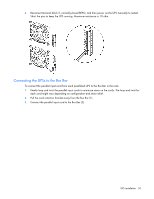
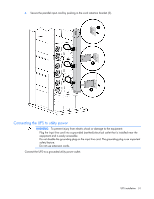
WARNING: To meet the requirements stated in NEC (NFPA 70) Articles 645-10 and 645-11, a UPS installed in a computer equipment room must be connected to a REPO circuit. NOTE: Wire the connector block using stranded, nonshielded wire (AWG #22 - #18, or equivalent). HP recommends using different colors for the positive and negative wires. To avoid inadvertant EPO: • Minimize wire strain while connecting the REPO port. • Avoid allowing the wires to hang in the rear of the UPS. • Use tie wraps and tie wrap blocks to secure the wires tightly to the rack and the rear of the UPS. For more information about the REPO port, see "REPO port (on page 10)" . For information about verifying the REPO connection, see "Verifying the REPO port connection (on page 71)" . Connecting to a normally-open contact IMPORTANT: The remote switch must be in the open position to enable power to the UPS output. You can install an optional REPO circuit that shuts down the entire parallel system using a single switch. To install a REPO switch for a parallel system, the selected REPO command (NO or NC) contacts from each UPS in the system must be in parallel. To install a REPO switch for a parallel system: 1. Verify that the UPS system is powered down and all power sources are removed. For more information, see "Powering down the parallel system (on page 73)." 2. Mount the remote REPO switch. HP recommends mounting the REPO switch near the operator's consoles or near the exit doors. For enclosure dimensions and wiring knockouts, see the REPO switch manufacturer's installation instructions. UPS installation 46
-
 1
1 -
2
-
3
-
4
-
5
-
6
-
7
-
8
-
9
-
10
-
11
-
12
-
13
-
14
-
15
-
16
-
17
-
18
-
19
-
20
-
21
-
22
-
23
-
24
-
25
-
26
-
27
-
28
-
29
-
30
-
31
-
32
-
33
-
34
-
35
-
36
-
37
-
38
-
39
-
40
-
 41
41 -
 42
42 -
 43
43 -
 44
44 -
 45
45 -
 46
46 -
 47
47 -
 48
48 -
 49
49 -
 50
50 -
 51
51 -
52
-
53
-
54
-
55
-
56
-
57
-
58
-
59
-
60
-
61
-
62
-
63
-
64
-
65
-
66
-
67
-
68
-
69
-
70
-
71
-
72
-
73
-
74
-
75
-
76
-
77
-
78
-
79
-
80
-
81
-
82
-
83
-
84
-
85
-
86
-
87
-
88
-
89
-
90
-
91
-
92
-
93
-
94
-
95
-
96
-
97
-
98
-
99
-
100
-
101
-
102
-
103
-
104
-
105
-
106
-
107
-
108
-
109
-
110
-
111
-
112
-
113
-
114
-
115
 |
 |
