HP RP36000/3 HP 3 Phase UPS User Guide - Page 55
ERM installation, Preparing to install the hardware, Tools and materials, Selecting a site
 |
View all HP RP36000/3 manuals
Add to My Manuals
Save this manual to your list of manuals |
Page 55 highlights
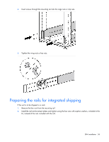
ERM installation Preparing to install the hardware Before installing the hardware: 1. Be sure the necessary tools and materials (on page 13) are available. 2. Select an installation site ("Selecting a site" on page 14). 3. Prepare the equipment ("Readying the equipment" on page 14) for installation in the rack. Tools and materials The following tools are required for installation: • Phillips screwdriver • 10-mm hex-nut wrench • T-25 Torx driver A cage nut-fitting tool is supplied with the rack. Selecting a site WARNING: To prevent fire or electric shock, install the unit in a temperature- and humidity-controlled indoor environment, free of conductive contaminants. When selecting a site, consider the following factors: • Elevated operating ambient temperature-If the equipment is installed in a closed or multi-unit rack assembly, the operating ambient temperature of the rack environment might be greater than room ambient temperature. Install the equipment in an environment compatible with the operating temperature ("Environmental specifications" on page 103). • Reduced air flow-In the rack, the rate of air flow required for safe operation of the equipment must not be compromised. • Circuit overloading-Consideration should be given to the connection of the equipment to the supply circuit and the effect that overloading of the circuits might have on overcurrent protection and supply wiring. Appropriate consideration of equipment nameplate ratings should be used when addressing this concern. • Reliable earthing-Reliable earthing of rack-mounted equipment should be maintained. Particular attention should be given to supply connections other than direct connections to the branch circuit, such as the use of power strips. • Electrical requirements-All models require a dedicated (unshared) branch circuit, suitably rated for the specific UPS as stated in "Input specifications" . ERM installation 55
-
 1
1 -
2
-
3
-
4
-
5
-
6
-
7
-
8
-
9
-
10
-
11
-
12
-
13
-
14
-
15
-
16
-
17
-
18
-
19
-
20
-
21
-
22
-
23
-
24
-
25
-
26
-
27
-
28
-
29
-
30
-
31
-
32
-
33
-
34
-
35
-
36
-
37
-
38
-
39
-
40
-
41
-
42
-
43
-
44
-
45
-
46
-
47
-
48
-
49
-
 50
50 -
 51
51 -
 52
52 -
 53
53 -
 54
54 -
 55
55 -
 56
56 -
 57
57 -
 58
58 -
 59
59 -
 60
60 -
61
-
62
-
63
-
64
-
65
-
66
-
67
-
68
-
69
-
70
-
71
-
72
-
73
-
74
-
75
-
76
-
77
-
78
-
79
-
80
-
81
-
82
-
83
-
84
-
85
-
86
-
87
-
88
-
89
-
90
-
91
-
92
-
93
-
94
-
95
-
96
-
97
-
98
-
99
-
100
-
101
-
102
-
103
-
104
-
105
-
106
-
107
-
108
-
109
-
110
-
111
-
112
-
113
-
114
-
115
 |
 |