HP Server rp7420 Installation Guide, Fifth Edition - HP 9000 rp7420 Server - Page 46
Wheel Kit Installation, Table 3-1, Wheel Kit Packing List
 |
View all HP Server rp7420 manuals
Add to My Manuals
Save this manual to your list of manuals |
Page 46 highlights
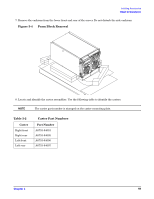
Installing Accessories Wheel Kit Installation Wheel Kit Installation Compare the packing list with the contents of the wheel kit before beginning the installation. Table 3-1 Wheel Kit Packing List Part Number A6753-04013 A6753-04002 A6753-04003 A6753-04004 A6753-00007 A6753-04001 A6753-04005 A6753-04006 A6753-04007 0515-2478 A6093-44013 Not Applicable Description Wheel Kit consisting of the following components: Right side caster cover Left side caster cover Top cover Caster cover Right front caster assembly Right rear caster assembly Left front caster assembly Left rear caster assembly M4 x 0.7 8mm T15 steel zinc machine screw (used to attach each caster to the chassis) Plywood nnloading ramp Phillips head wood screw (used to attach the ramp to the pallet) Quantity 1 1 1 1 2 1 1 1 1 4 1 2 Tools Required for Installation The following list provides the installer with the recommended tools to perform the wheel kit installation. • Diagonal side cutters • Safety glasses • Torx screwdriver with T-15 bit • Phillips head screwdriver WARNING Wear protective glasses while cutting the plastic bands around the shipping container. These bands are under tension. When cut, they can spring back and cause serious eye injury. 46 Chapter 3
-
 1
1 -
2
-
3
-
4
-
5
-
6
-
7
-
8
-
9
-
10
-
11
-
12
-
13
-
14
-
15
-
16
-
17
-
18
-
19
-
20
-
21
-
22
-
23
-
24
-
25
-
26
-
27
-
28
-
29
-
30
-
31
-
32
-
33
-
34
-
35
-
36
-
37
-
38
-
39
-
40
-
 41
41 -
 42
42 -
 43
43 -
 44
44 -
 45
45 -
 46
46 -
 47
47 -
 48
48 -
 49
49 -
 50
50 -
 51
51 -
52
-
53
-
54
-
55
-
56
-
57
-
58
-
59
-
60
-
61
-
62
-
63
-
64
-
65
-
66
-
67
-
68
-
69
-
70
-
71
-
72
-
73
-
74
-
75
-
76
-
77
-
78
-
79
-
80
 |
 |
