HP Server rp7420 Installation Guide, Fifth Edition - HP 9000 rp7420 Server - Page 61
Voltage Reference Points for IEC 320 C19 Plug, Table 4-1, Single Phase Voltage Examples
 |
View all HP Server rp7420 manuals
Add to My Manuals
Save this manual to your list of manuals |
Page 61 highlights
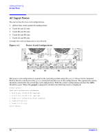
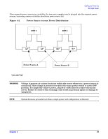
Cabling and Power Up Voltage Check Voltage Range Verification of Receptacle This measures the voltage between L1 and L2, L1 to ground, and L2 to ground. Three separate measurements are performed during this procedure. See Figure 4-3 for voltage reference points when performing the following measurements. Figure 4-3 Voltage Reference Points for IEC 320 C19 Plug IMPORTANT These measurements must be performed for every power cord that plugs into the HP 9000 rp7420 Server. Step 1. Measure the voltage between L1 and L2. This is considered to be a phase-to-phase measurement in North America. In Europe and certain parts of Asia-Pacific, this measurement is referred to as a phase-to-neutral measurement. The expected voltage measured should be between 200-240 V AC regardless of the geographic region. Step 2. Measure the voltage between L1 and ground. In North America, verify this voltage is between 100-120 V AC. In Europe and certain parts of Asia-Pacific, verify this voltage is between 200-240 V AC. Step 3. Measure the voltage between L2 and ground. In North America, verify this voltage is between 100-120 V AC. In Europe and certain parts of Asia-Pacific, verify this voltage is 0 (zero) V AC. Table 4-1 provides single phase voltage measurement examples dependent on the geographic region where these measurements are taken. Table 4-1 Single Phase Voltage Examples Japan North America Europea L1-L2 210 V 208 V or 240 V 230 V L1-GND 105 V 120 V 230 V L2-GND 105 V 120 V 0 V a. In some European countries there might not be a polarization. Chapter 4 61
-
 1
1 -
2
-
3
-
4
-
5
-
6
-
7
-
8
-
9
-
10
-
11
-
12
-
13
-
14
-
15
-
16
-
17
-
18
-
19
-
20
-
21
-
22
-
23
-
24
-
25
-
26
-
27
-
28
-
29
-
30
-
31
-
32
-
33
-
34
-
35
-
36
-
37
-
38
-
39
-
40
-
41
-
42
-
43
-
44
-
45
-
46
-
47
-
48
-
49
-
50
-
51
-
52
-
53
-
54
-
55
-
 56
56 -
 57
57 -
 58
58 -
 59
59 -
 60
60 -
 61
61 -
 62
62 -
 63
63 -
 64
64 -
 65
65 -
 66
66 -
67
-
68
-
69
-
70
-
71
-
72
-
73
-
74
-
75
-
76
-
77
-
78
-
79
-
80
 |
 |
