HP SlateBook 10-h010nr HP SlateBook 10 x2 PC Maintenance and Service Guide - Page 38
Remove the bezel, Battery see
 |
View all HP SlateBook 10-h010nr manuals
Add to My Manuals
Save this manual to your list of manuals |
Page 38 highlights
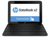
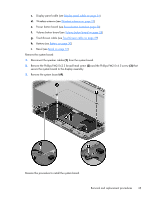
3. Disconnect all external devices from the tablet. 4. Remove the display enclosure (see Display enclosure on page 20), and then remove the following components: a. Rear webcam (see Rear webcam on page 21) b. Front webcam (see Front webcam on page 23) c. Display panel cable (see Display panel cable on page 24) d. Wireless antenna (see Wireless antenna on page 25) e. Power button board (see Power button board on page 26) f. Volume button board (see Volume button board on page 28) g. TouchScreen cable (see TouchScreen cable on page 29) h. Battery (see Battery on page 30) Remove the bezel: 1. Remove the two Phillips PM2.0×2.5 screws (1) and the three Phillips PM2.0×4.5 screws (2) that secure the bezel to the display assembly. 2. Remove the bezel (3) from the display assembly. Reverse this procedure to install the bezel. 32 Chapter 4 Removal and replacement procedures preliminary requirements
-
 1
1 -
2
-
3
-
4
-
5
-
6
-
7
-
8
-
9
-
10
-
11
-
12
-
13
-
14
-
15
-
16
-
17
-
18
-
19
-
20
-
21
-
22
-
23
-
24
-
25
-
26
-
27
-
28
-
29
-
30
-
31
-
32
-
 33
33 -
 34
34 -
 35
35 -
 36
36 -
 37
37 -
 38
38 -
 39
39 -
 40
40 -
 41
41 -
 42
42 -
 43
43 -
44
-
45
-
46
-
47
-
48
-
49
-
50
-
51
-
52
-
53
-
54
-
55
-
56
-
57
-
58
 |
 |
