HP SlateBook 10-h010nr HP SlateBook 10 x2 PC Maintenance and Service Guide - Page 42
Keyboard base component replacement procedures, Bottom cover
 |
View all HP SlateBook 10-h010nr manuals
Add to My Manuals
Save this manual to your list of manuals |
Page 42 highlights
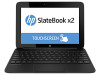
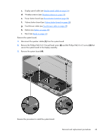
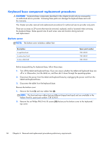
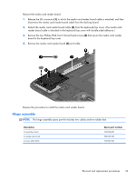
Keyboard base component replacement procedures CAUTION: Keyboard base components described in this chapter should only be accessed by an authorized service provider. Accessing these parts can damage the keyboard base and void the warranty. This chapter provides removal and replacement procedures for authorized service provider only parts. There are as many as 29 screws that must be removed, replaced, and/or loosened when servicing the keyboard base. Make special note of each screw size and location during removal and replacement. Bottom cover NOTE: The bottom cover includes a rubber foot. Description In royal blue finish In smoke silver finish In snow white finish Spare part number 728140-001 728138-001 728139-001 Before disassembling the keyboard base, follow these steps: 1. Turn off the tablet and keyboard base. If you are unsure whether the tablet and keyboard base are off or in Hibernation, turn the tablet on, and then shut it down through the operating system. 2. Disconnect the power from the tablet and keyboard base by unplugging the power cord from the tablet and keyboard base. 3. Disconnect the tablet from the keyboard base. Remove the bottom cover: 1. Remove the front (1) and rear rubber feet (2). NOTE: The front and rear rubber feet are different shaped and sized and are available in the Rubber Feet Kit, spare part number 728153-001. 2. Remove the six Phillips PM2.0×6.35 screws (3) that secure the bottom cover to the keyboard/ top cover. 36 Chapter 4 Removal and replacement procedures preliminary requirements
-
 1
1 -
2
-
3
-
4
-
5
-
6
-
7
-
8
-
9
-
10
-
11
-
12
-
13
-
14
-
15
-
16
-
17
-
18
-
19
-
20
-
21
-
22
-
23
-
24
-
25
-
26
-
27
-
28
-
29
-
30
-
31
-
32
-
33
-
34
-
35
-
36
-
 37
37 -
 38
38 -
 39
39 -
 40
40 -
 41
41 -
 42
42 -
 43
43 -
 44
44 -
 45
45 -
 46
46 -
 47
47 -
48
-
49
-
50
-
51
-
52
-
53
-
54
-
55
-
56
-
57
-
58
 |
 |
