HP Spectre 13-3018ca HP Spectre 13 Ultrabook - Maintenance and Service Guide - Page 40
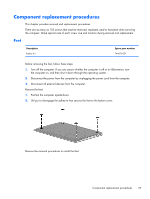
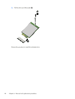
Remove the Phillips PM2.0×3.0 screw, Remove the WLAN module
 |
View all HP Spectre 13-3018ca manuals
Add to My Manuals
Save this manual to your list of manuals |
Page 40 highlights
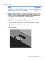
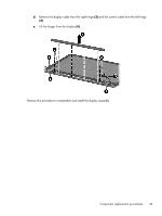
Remove the WLAN module: 1. Disconnect the WLAN antenna cables (1) from the terminals on the WLAN module. NOTE: The WLAN antenna cable labeled "1" connects to the WLAN module "Main" terminal labeled "1". The WLAN antenna cable labeled "2" connects to the WLAN module "Aux" terminal labeled "2". If the computer is equipped with an 802.11a/b/g/n WLAN module, the yellow WLAN antenna cable connects to the middle terminal on the WLAN module. 2. Remove the Phillips PM2.0×3.0 screw (2) that secures the WLAN module to the base enclosure. 3. Remove the WLAN module (3) by pulling the module away from the slot. NOTE: WLAN modules are designed with a notch to prevent incorrect insertion. NOTE: If the WLAN antennas are not connected to the terminals on the WLAN module, the protective sleeves must be installed on the antenna connectors, as shown in the following illustration. Reverse this procedure to install the WLAN module. 32 Chapter 4 Removal and replacement procedures
-
 1
1 -
2
-
3
-
4
-
5
-
6
-
7
-
8
-
9
-
10
-
11
-
12
-
13
-
14
-
15
-
16
-
17
-
18
-
19
-
20
-
21
-
22
-
23
-
24
-
25
-
26
-
27
-
28
-
29
-
30
-
31
-
32
-
33
-
34
-
 35
35 -
 36
36 -
 37
37 -
 38
38 -
 39
39 -
 40
40 -
 41
41 -
 42
42 -
 43
43 -
 44
44 -
 45
45 -
46
-
47
-
48
-
49
-
50
-
51
-
52
-
53
-
54
-
55
-
56
-
57
-
58
-
59
-
60
-
61
-
62
-
63
-
64
-
65
-
66
-
67
-
68
-
69
-
70
-
71
-
72
-
73
-
74
-
75
-
76
-
77
-
78
-
79
-
80
 |
 |