HP Spectre 13-3018ca HP Spectre 13 Ultrabook - Maintenance and Service Guide - Page 42
Remove the 7 Phillips PM2.5×4.0 screws
 |
View all HP Spectre 13-3018ca manuals
Add to My Manuals
Save this manual to your list of manuals |
Page 42 highlights
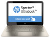
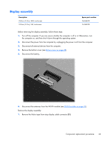
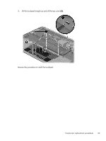
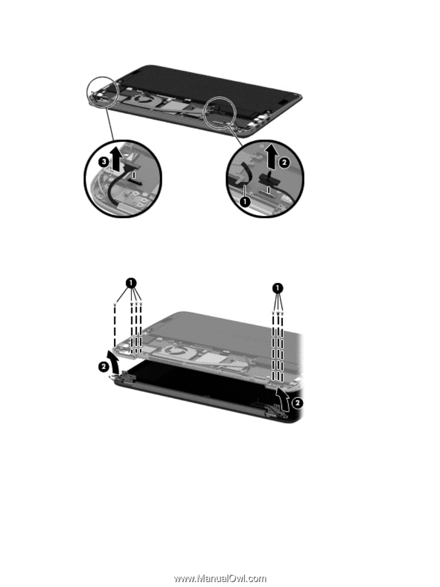
2. Disconnect the display panel cable (2) and the control cable (3) from the system board. 3. Remove the 7 Phillips PM2.5×4.0 screws (1) that secure the display assembly to the computer. 4. Rotate the computer upward to open the display hinges, and then separate the display from the computer (2). 5. If it is necessary to remove the clutch cover or the display hinges: a. Remove the clutch cover (the plastic piece on the bottom of the display) by pulling it straight up to disengage it (1). b. Remove the 4 Phillips PM2.5×5.0 screws (2 from each hinge) that secure the hinges to the display. c. Remove the antennas and the control cable from the left hinge (2). 34 Chapter 4 Removal and replacement procedures
-
 1
1 -
2
-
3
-
4
-
5
-
6
-
7
-
8
-
9
-
10
-
11
-
12
-
13
-
14
-
15
-
16
-
17
-
18
-
19
-
20
-
21
-
22
-
23
-
24
-
25
-
26
-
27
-
28
-
29
-
30
-
31
-
32
-
33
-
34
-
35
-
36
-
 37
37 -
 38
38 -
 39
39 -
 40
40 -
 41
41 -
 42
42 -
 43
43 -
 44
44 -
 45
45 -
 46
46 -
 47
47 -
48
-
49
-
50
-
51
-
52
-
53
-
54
-
55
-
56
-
57
-
58
-
59
-
60
-
61
-
62
-
63
-
64
-
65
-
66
-
67
-
68
-
69
-
70
-
71
-
72
-
73
-
74
-
75
-
76
-
77
-
78
-
79
-
80
 |
 |
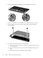
2.
Disconnect the display panel cable
(2)
and the control cable
(3)
from the system board.
3.
Remove the 7 Phillips PM2.5×4.0 screws
(1)
that secure the display assembly to the computer.
4.
Rotate the computer upward to open the display hinges, and then separate the display from
the computer
(2)
.
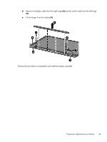
5.
If it is necessary to remove the clutch cover or the display hinges:
a.
Remove the clutch cover (the plastic piece on the bottom of the display) by pulling it straight
up to disengage it
(1)
.
b.
Remove the 4 Phillips PM2.5×5.0 screws (2 from each hinge) that secure the hinges to the
display.
c.
Remove the antennas and the control cable from the left hinge
(2)
.
34
Chapter 4
Removal and replacement procedures