HP Spectre 13-3018ca HP Spectre 13 Ultrabook - Maintenance and Service Guide - Page 61
Keyboard and top cover, Remove the 12 Phillips PM1.0×2.0 screws
 |
View all HP Spectre 13-3018ca manuals
Add to My Manuals
Save this manual to your list of manuals |
Page 61 highlights
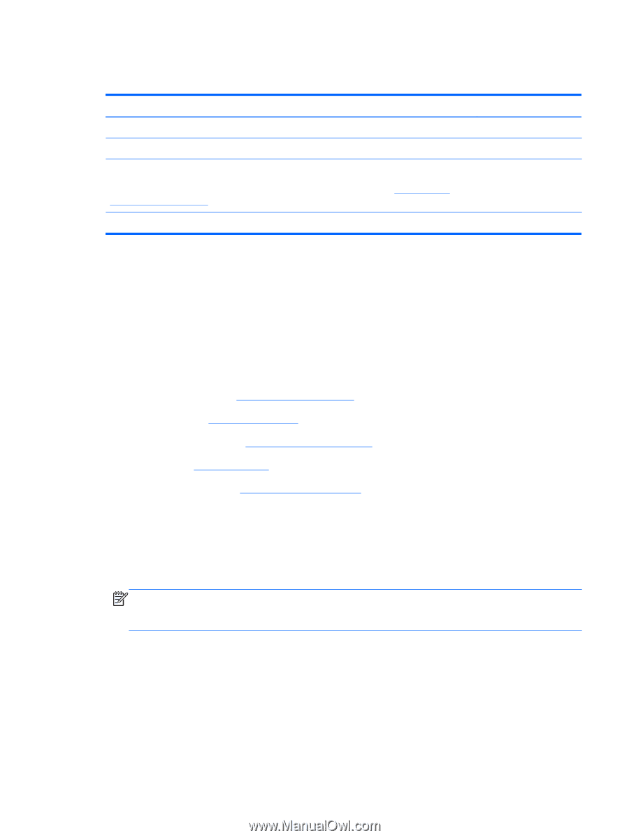
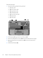
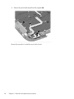
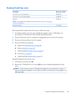
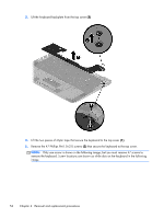
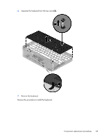
Keyboard and top cover Description Top cover for use in the United States Top cover for use in the United Kingdom Keyboard NOTE: For a complete list of keyboards and associated country codes, see Sequential part number listing on page 19. Keyboard backplate Spare part number 744381-001 744382-001 743897-xx1 744366-001 Before separating the keyboard from the top cover, follow these steps: 1. Turn off the computer. If you are unsure whether the computer is off or in Hibernation, turn the computer on, and then shut it down through the operating system. 2. Disconnect the power from the computer by unplugging the power cord from the computer. 3. Disconnect all external devices from the computer. 4. Remove the following components: a. Bottom cover (see Bottom cover on page 28) b. Battery (see Battery on page 45) c. WLAN module (see WLAN module on page 31) d. Fan (see Fan on page 40) e. System board (see System board on page 47) Separate the keyboard from the top cover: 1. Lift the tape over the left screw (1). 2. Remove the 12 Phillips PM1.0×2.0 screws (2) that secure the keyboard backplate to the top cover. NOTE: Only one screw is shown in the following image, but you must remove 12 screws to remove the keyboard backplate. Screw locations are shown as while dots on the backplate in the following image. Component replacement procedures 53
-
 1
1 -
2
-
3
-
4
-
5
-
6
-
7
-
8
-
9
-
10
-
11
-
12
-
13
-
14
-
15
-
16
-
17
-
18
-
19
-
20
-
21
-
22
-
23
-
24
-
25
-
26
-
27
-
28
-
29
-
30
-
31
-
32
-
33
-
34
-
35
-
36
-
37
-
38
-
39
-
40
-
41
-
42
-
43
-
44
-
45
-
46
-
47
-
48
-
49
-
50
-
51
-
52
-
53
-
54
-
55
-
 56
56 -
 57
57 -
 58
58 -
 59
59 -
 60
60 -
 61
61 -
 62
62 -
 63
63 -
 64
64 -
 65
65 -
 66
66 -
67
-
68
-
69
-
70
-
71
-
72
-
73
-
74
-
75
-
76
-
77
-
78
-
79
-
80
 |
 |