HP Spectre 13-ae000 Maintenance and Service Guide - Page 43
Fans, to which infrared sensor board cable is connected,
 |
View all HP Spectre 13-ae000 manuals
Add to My Manuals
Save this manual to your list of manuals |
Page 43 highlights
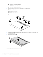
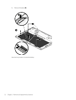
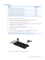
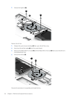
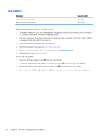
Fans Description Left fan (includes cable) Right fan (includes cable) Spare part number 942843-001 942842-001 Before removing the fans, follow these steps: 1. Shut down the computer. If you are unsure whether the computer is off or in Hibernation, turn the computer on, and then shut it down through the operating system. 2. Disconnect all external devices connected to the computer. 3. Disconnect the power from the computer by first unplugging the power cord from the AC outlet, and then unplugging the AC adapter from the computer. 4. Remove the bottom cover (see Bottom cover on page 29). 5. Disconnect the battery cable from the system board (see Battery on page 31). Remove the right fan: 1. Release the system board shielding (1) that covers the infrared sensor board cable and connector. 2. Release the webcam/microphone module cable (2) from the retention clip built into the right fan. 3. Disconnect the right fan cable (3) from the system board. 4. Release the zero insertion force (ZIF) connector (4) to which infrared sensor board cable is connected, and then disconnect the infrared sensor board cable from the system board. 5. Detach the infrared sensor board cable (5) from the system board. (The infrared sensor board cable is attached to the system board with double-sided adhesive.) 6. Remove the Phillips M2.0×5.2 screw (6) and the Phillips M2.0×2.8 screw (7) that secure the right fan to the keyboard/top cover. Component replacement procedures 35
-
 1
1 -
2
-
3
-
4
-
5
-
6
-
7
-
8
-
9
-
10
-
11
-
12
-
13
-
14
-
15
-
16
-
17
-
18
-
19
-
20
-
21
-
22
-
23
-
24
-
25
-
26
-
27
-
28
-
29
-
30
-
31
-
32
-
33
-
34
-
35
-
36
-
37
-
 38
38 -
 39
39 -
 40
40 -
 41
41 -
 42
42 -
 43
43 -
 44
44 -
 45
45 -
 46
46 -
 47
47 -
 48
48 -
49
-
50
-
51
-
52
-
53
-
54
-
55
-
56
-
57
-
58
-
59
-
60
-
61
-
62
-
63
-
64
-
65
-
66
-
67
-
68
-
69
-
70
-
71
-
72
-
73
-
74
-
75
-
76
-
77
-
78
-
79
-
80
-
81
 |
 |