HP Spectre 13-ae000 Maintenance and Service Guide - Page 60
Display panel ZIF connector cable, Webcam-microphone module cable
 |
View all HP Spectre 13-ae000 manuals
Add to My Manuals
Save this manual to your list of manuals |
Page 60 highlights
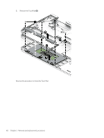
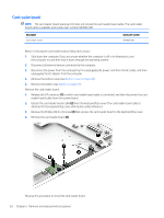
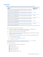
(6) Fingerprint reader module ZIF connector cable (7) Rear speaker cables (8) WLAN module antenna cables NOTE: The #1/white WLAN antenna cable connects to the WLAN module "#1/Main" terminal. The #2/ black WLAN antenna cable connects to the WLAN module "#2/Aux" terminal. (9) Webcam-microphone module cable (10) Display panel ZIF connector cable (11) Audio jack board ZIF connector cable 2. Remove the two Phillips M2.0×2.8 screws (1) that secure the system board to the keyboard/top cover. 52 Chapter 5 Removal and replacement procedures
-
 1
1 -
2
-
3
-
4
-
5
-
6
-
7
-
8
-
9
-
10
-
11
-
12
-
13
-
14
-
15
-
16
-
17
-
18
-
19
-
20
-
21
-
22
-
23
-
24
-
25
-
26
-
27
-
28
-
29
-
30
-
31
-
32
-
33
-
34
-
35
-
36
-
37
-
38
-
39
-
40
-
41
-
42
-
43
-
44
-
45
-
46
-
47
-
48
-
49
-
50
-
51
-
52
-
53
-
54
-
 55
55 -
 56
56 -
 57
57 -
 58
58 -
 59
59 -
 60
60 -
 61
61 -
 62
62 -
 63
63 -
 64
64 -
 65
65 -
66
-
67
-
68
-
69
-
70
-
71
-
72
-
73
-
74
-
75
-
76
-
77
-
78
-
79
-
80
-
81
 |
 |
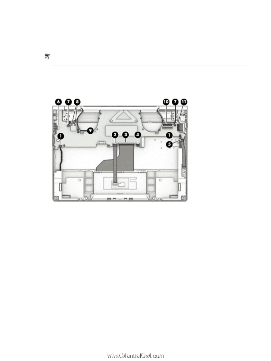
(6)
Fingerprint reader module ZIF connector cable
(7)
Rear speaker cables
(8)
WLAN module antenna cables
NOTE:
The #1/white WLAN antenna cable connects to the WLAN module "#1/Main" terminal. The #2/
black WLAN antenna cable connects to the WLAN module "#2/Aux" terminal.
(9)
Webcam-microphone module cable
(10)
Display panel ZIF connector cable
(11)
Audio jack board ZIF connector cable
2.
Remove the two Phillips M2.0×2.8 screws
(1)
that secure the system board to the keyboard/top cover.
52
Chapter 5
Removal and replacement procedures