HP Spectre 13-ae000 Maintenance and Service Guide - Page 51
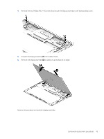
Reverse this procedure to install the display assembly
 |
View all HP Spectre 13-ae000 manuals
Add to My Manuals
Save this manual to your list of manuals |
Page 51 highlights
4. Remove the four Phillips M2.5×4.6 screws that secure the display assembly to the keyboard/top cover. 5. Position the display assembly (1) in the tablet mode. 6. Remove the display assembly (2) by sliding it up and back at an angle. Reverse this procedure to install the display assembly. Component replacement procedures 43
-
 1
1 -
2
-
3
-
4
-
5
-
6
-
7
-
8
-
9
-
10
-
11
-
12
-
13
-
14
-
15
-
16
-
17
-
18
-
19
-
20
-
21
-
22
-
23
-
24
-
25
-
26
-
27
-
28
-
29
-
30
-
31
-
32
-
33
-
34
-
35
-
36
-
37
-
38
-
39
-
40
-
41
-
42
-
43
-
44
-
45
-
 46
46 -
 47
47 -
 48
48 -
 49
49 -
 50
50 -
 51
51 -
 52
52 -
 53
53 -
 54
54 -
 55
55 -
 56
56 -
57
-
58
-
59
-
60
-
61
-
62
-
63
-
64
-
65
-
66
-
67
-
68
-
69
-
70
-
71
-
72
-
73
-
74
-
75
-
76
-
77
-
78
-
79
-
80
-
81
 |
 |
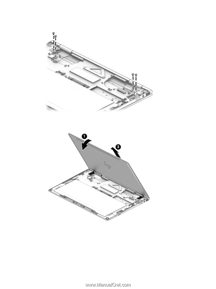
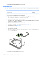
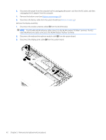
4.
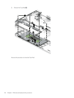
Remove the four Phillips M2.5×4.6 screws that secure the display assembly to the keyboard/top cover.
5.
Position the display assembly
(1)
in the tablet mode.
6.
Remove the display assembly
(2)
by sliding it up and back at an angle.
Reverse this procedure to install the display assembly.
Component replacement procedures
43