HP Spectre XT TouchSmart Ultrabook CTO 15t-4000 HP SpectreXT TouchSmart Mainte - Page 65
Power connector cable, and the routing channel built into the top cover.
 |
View all HP Spectre XT TouchSmart Ultrabook CTO 15t-4000 manuals
Add to My Manuals
Save this manual to your list of manuals |
Page 65 highlights
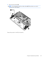
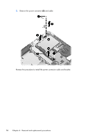
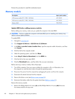
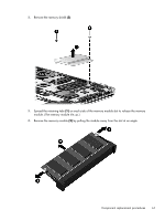
Power connector cable Description Power connector cable (includes bracket) Spare part number 700802-001 Before removing the power connector cable, follow these steps: 1. Turn off the computer. If you are unsure whether the computer is off or in Hibernation, turn the computer on, and then shut it down through the operating system. 2. Disconnect the power from the computer by unplugging the power cord from the computer. 3. Disconnect all external devices from the computer. 4. Remove the bottom cover (see Bottom cover on page 33). 5. Disconnect the battery cable from the system board (see Battery on page 35). Remove the power connector cable: 1. Disconnect the power cable (1) from the system board. 2. Release the power cable from the clips (2) and the routing channel built into the top cover. 3. Remove the two Phillips PM2.0×4.5 screws (3) that secure the power connector and bracket to the top cover. 4. Remove the power connector bracket (4). Component replacement procedures 57
-
 1
1 -
2
-
3
-
4
-
5
-
6
-
7
-
8
-
9
-
10
-
11
-
12
-
13
-
14
-
15
-
16
-
17
-
18
-
19
-
20
-
21
-
22
-
23
-
24
-
25
-
26
-
27
-
28
-
29
-
30
-
31
-
32
-
33
-
34
-
35
-
36
-
37
-
38
-
39
-
40
-
41
-
42
-
43
-
44
-
45
-
46
-
47
-
48
-
49
-
50
-
51
-
52
-
53
-
54
-
55
-
56
-
57
-
58
-
59
-
 60
60 -
 61
61 -
 62
62 -
 63
63 -
 64
64 -
 65
65 -
 66
66 -
 67
67 -
 68
68 -
 69
69 -
 70
70 -
71
-
72
-
73
-
74
-
75
-
76
-
77
-
78
-
79
-
80
-
81
-
82
-
83
-
84
-
85
-
86
-
87
-
88
-
89
-
90
-
91
-
92
-
93
-
94
-
95
-
96
-
97
-
98
-
99
-
100
-
101
 |
 |
