HP StorageWorks 2/8-EL SAN Switch 2/8 V3.1.x - Installation Guide - Page 34
Attaching the Fixed Rack Mount Kit rails to the switch
 |
View all HP StorageWorks 2/8-EL manuals
Add to My Manuals
Save this manual to your list of manuals |
Page 34 highlights
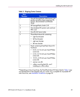
Installing the SAN Switch 2/8 2. Repeat steps 1a through 1d to attach right front bracket (Item 8) to the right side of the switch, see Figure 6. 2 5 1 4 3 6 7 8 SHR-2501A 1 Left front bracket 2 Left rear bracket 3 6-32 x 5/16-inch pan head Phillips screws 4 Right rear bracket 5 10-32 x 5/8-inch pan head Phillips screws 6 Retainer nuts 7 8-32 x 5/16-inch pan head Phillips screws 8 Right front bracket Figure 6: Attaching the Fixed Rack Mount Kit rails to the switch 3. Position the switch in the rack as shown in Figure 6, providing temporary support under the switch (use clamps if necessary). 4. To secure the front brackets to the rack's front rails, attach the right front bracket (Item 8) to the right front rack rail using two 10-32 x 5/8 inch screws (Item 5) and two retainer nuts (Item 6). 5. Repeat step 4 to attach the left front brackets (Item 1) to the left front rack rail. 6. Tighten all screws and torque to 25-inch pounds. 34 SAN Switch 2/8 Version 3.1.x Installation Guide
-
 1
1 -
2
-
3
-
4
-
5
-
6
-
7
-
8
-
9
-
10
-
11
-
12
-
13
-
14
-
15
-
16
-
17
-
18
-
19
-
20
-
21
-
22
-
23
-
24
-
25
-
26
-
27
-
28
-
 29
29 -
 30
30 -
 31
31 -
 32
32 -
 33
33 -
 34
34 -
 35
35 -
 36
36 -
 37
37 -
 38
38 -
 39
39 -
40
-
41
-
42
-
43
-
44
-
45
-
46
-
47
-
48
-
49
-
50
-
51
-
52
-
53
-
54
-
55
-
56
-
57
-
58
-
59
-
60
-
61
-
62
-
63
-
64
-
65
-
66
-
67
-
68
-
69
-
70
-
71
-
72
-
73
-
74
-
75
-
76
-
77
-
78
-
79
-
80
-
81
-
82
-
83
-
84
-
85
-
86
-
87
-
88
-
89
-
90
-
91
-
92
-
93
-
94
-
95
-
96
-
97
-
98
-
99
-
100
-
101
-
102
-
103
-
104
-
105
-
106
-
107
-
108
-
109
-
110
-
111
-
112
-
113
-
114
 |
 |
