HP dc73 Technical Reference Guide: HP Compaq dc7800 Series Business Desktop Co - Page 40
Table 4-1 shows the standard configuration of device numbers and IDSEL connections for, components
 |
View all HP dc73 manuals
Add to My Manuals
Save this manual to your list of manuals |
Page 40 highlights
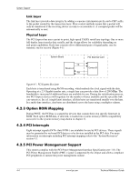
System Support Table 4-1 shows the standard configuration of device numbers and IDSEL connections for components and slots residing on a PCI 2.3 bus. Table 4-1 PCI Component Configuration Access PCI Component Q35 GMCH: Host/DMI Bridge Host/PCI Expr. Bridge Integrated Graphics Cntlr. PCI Express x16 graphics slot 82801EB ICH9 PCI Bridge LPC Bridge Serial ATA Controller #1 SMBus Controller Serial ATA Controller #2 Thermal System USB 1.1 Controller #1 USB 1.1 Controller #2 USB 1.1 Controller #3 USB 1.1 Controller #4 USB 1.1 Controller #5 USB 2.0 Controller #1 USB 2.0 Controller #2 Network Interface Controller Intel HD audio controller PCIe port 1 PCIe port 2 PCIe port 3 PCIe port 4 PCIe port 5 PCIe port 6 PCI 2.3 slot 1 PCI 2.3 slot 2 PCI 2.3 slot 3 PCIe x1 slot 1 PCIe x1 slot 2 Notes Function # 0 0 0 0 0 0 2 3 [1] 5 6 0 1 2 3 [2] 1 7 7 0 0 0 [3] 1 [1] 2 [1] 3 [1] 4 5 [3] 0 [3] 0 [4] 0 [3] 0 [3] 0 Device # 28 1 2 0 30 31 31 31 31 31 29 29 29 29 [2] 26 29 26 25 27 28 28 28 28 28 28 4 11 10 0 0 PCI Bus # 0 0 0 1 0 0 0 0 0 0 0 0 0 0 0 0 0 0 0 0 0 0 0 0 0 7 7 7 32 48 IDSEL Wired to: ---- AD20 AD25 AD27 NOTES: [1] Function not used in these systems. [2] Mapping for USB 1.1 Controller #4 if USB ports 9 and 10 and USB 2.0 Controller #2 are disabled. Otherwise, mapping for USB 1.1 controller #4 is F0:D25. [3] SFF and CMT form factors only. [4] CMT form factor only 4-2 www.hp.com Technical Reference Guide
-
 1
1 -
2
-
3
-
4
-
5
-
6
-
7
-
8
-
9
-
10
-
11
-
12
-
13
-
14
-
15
-
16
-
17
-
18
-
19
-
20
-
21
-
22
-
23
-
24
-
25
-
26
-
27
-
28
-
29
-
30
-
31
-
32
-
33
-
34
-
 35
35 -
 36
36 -
 37
37 -
 38
38 -
 39
39 -
 40
40 -
 41
41 -
 42
42 -
 43
43 -
 44
44 -
 45
45 -
46
-
47
-
48
-
49
-
50
-
51
-
52
-
53
-
54
-
55
-
56
-
57
-
58
-
59
-
60
-
61
-
62
-
63
-
64
-
65
-
66
-
67
-
68
-
69
-
70
-
71
-
72
-
73
-
74
-
75
-
76
-
77
-
78
-
79
-
80
-
81
-
82
-
83
-
84
-
85
-
86
-
87
-
88
-
89
-
90
-
91
-
92
-
93
-
94
-
95
-
96
-
97
-
98
-
99
-
100
-
101
-
102
 |
 |
