HP dc73 Technical Reference Guide: HP Compaq dc7800 Series Business Desktop Co - Page 84
CMT Power Distribution
 |
View all HP dc73 manuals
Add to My Manuals
Save this manual to your list of manuals |
Page 84 highlights
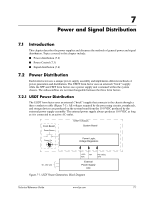
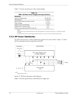
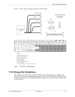
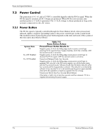
Power and Signal Distribution 7.2.3 CMT Power Distribution The CMT form factor uses a power supply unit internal to the system chassis. Figure 7-4 shows the block diagram for power generation in the CMT. Front Bezel Power Button Power On System Board CPU, slots, Chipsets, Logic, & Voltage Regulators +3.3 VDC 5 AUX +5 VDC +12 VDC +12 VccP Fan PS On Spd [1] -12 VDC +3.3 VDC +5 VDC +12 VDC Drives 90 - 264 VAC Power Supply Unit NOTE: [1] Not present on CMT. Figure 7-4. CMT Power Generation, Block Diagram Table 7-3 lists the specifications for the 365-watt power supply used in the CMT form factor. Table 7-3. CMT 365-Watt Power Supply Unit Specifications Input Line Voltage: 115-230 VAC (auto-ranging) Line Frequency Input (AC) Current +3.3 VDC Output +5.08 VDC Output +5.08 AUX Output +12 VDC Output +12 VDC Output (Vcpu) -12 VDC Output Range or Tolerance Min. Current Max. Surge Loading [1] Current Current [2] 90-264 VAC 47-63 Hz -+ 4 % + 3.3 % + 3.3 % + 5 % + 5 % + 10 % ---0.10 A 0.30 A 0.00 A 0.20 A 0.00 A 0.00 A --6.0 A 24.0 A 19.0 A 3.00 A 12.0 A 14.5 A 0.15 A ---24.0 A 19.0 A 3.00 A 14.5 A 17.5 A 0.15 A Max. Ripple ---50 mV 50 mV 50 mV 120 mV 200 mv 200 mV NOTES: Total continuous output power should not exceed 365 watts. Maximum surge power should not exceed 385 watts.. Maximum combined power of +5 and +3.3 VDC is 160 watts. [1] Minimum loading requirements must be met at all times to ensure normal operation and specification compliance. [2] Maximum surge duration for +12Vcpu is 1 second with 12-volt tolerance +/- 10%. 7-4 www.hp.com Technical Reference Guide
-
 1
1 -
2
-
3
-
4
-
5
-
6
-
7
-
8
-
9
-
10
-
11
-
12
-
13
-
14
-
15
-
16
-
17
-
18
-
19
-
20
-
21
-
22
-
23
-
24
-
25
-
26
-
27
-
28
-
29
-
30
-
31
-
32
-
33
-
34
-
35
-
36
-
37
-
38
-
39
-
40
-
41
-
42
-
43
-
44
-
45
-
46
-
47
-
48
-
49
-
50
-
51
-
52
-
53
-
54
-
55
-
56
-
57
-
58
-
59
-
60
-
61
-
62
-
63
-
64
-
65
-
66
-
67
-
68
-
69
-
70
-
71
-
72
-
73
-
74
-
75
-
76
-
77
-
78
-
 79
79 -
 80
80 -
 81
81 -
 82
82 -
 83
83 -
 84
84 -
 85
85 -
 86
86 -
 87
87 -
 88
88 -
 89
89 -
90
-
91
-
92
-
93
-
94
-
95
-
96
-
97
-
98
-
99
-
100
-
101
-
102
 |
 |
