HP dc73 Technical Reference Guide: HP Compaq dc7800 Series Business Desktop Co - Page 83
Table 7-2., SFF 240-Watt Power Supply Unit Specifications
 |
View all HP dc73 manuals
Add to My Manuals
Save this manual to your list of manuals |
Page 83 highlights
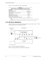
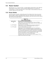
Power and Signal Distribution Table 7-2. SFF 240-Watt Power Supply Unit Specifications Input Line Voltage Line Frequency Input (AC) Current +3.3 VDC Output +5.08 VDC Output +5.08 AUX Output +12 VDC Output +12 VDC Output (Vcpu) --12 VDC Output Range/ Tolerance 90-264 VAC 47-63 Hz -+ 4% + 3.3 % + 3.3 % + 5 % + 5 % + 10 % Min. Current Loading [1] ---0.1 A 0.3 A 0.0 A 0.1 A 0.1 A 0.0 A Max. Current --5.0 A 15.0 A 17.0 A 3.0 A 7.5 A 11.0 A 0.15 A Surge Current [2] ---15.0 A 17.0 A 3.5 A 9.0 A 14.5 A 0.15 A Max. Ripple ---50 mV 50 mV 50 mV 120 mV 120 mv 200 mV NOTES: Total continuous power should not exceed 240 watts. Total surge power (
-
 1
1 -
2
-
3
-
4
-
5
-
6
-
7
-
8
-
9
-
10
-
11
-
12
-
13
-
14
-
15
-
16
-
17
-
18
-
19
-
20
-
21
-
22
-
23
-
24
-
25
-
26
-
27
-
28
-
29
-
30
-
31
-
32
-
33
-
34
-
35
-
36
-
37
-
38
-
39
-
40
-
41
-
42
-
43
-
44
-
45
-
46
-
47
-
48
-
49
-
50
-
51
-
52
-
53
-
54
-
55
-
56
-
57
-
58
-
59
-
60
-
61
-
62
-
63
-
64
-
65
-
66
-
67
-
68
-
69
-
70
-
71
-
72
-
73
-
74
-
75
-
76
-
77
-
 78
78 -
 79
79 -
 80
80 -
 81
81 -
 82
82 -
 83
83 -
 84
84 -
 85
85 -
 86
86 -
 87
87 -
 88
88 -
89
-
90
-
91
-
92
-
93
-
94
-
95
-
96
-
97
-
98
-
99
-
100
-
101
-
102
 |
 |

Technical Reference Guide
www.hp.com
7-3
Power and Signal Distribution
NOTES:
Total continuous power should not exceed 240 watts. Total surge power (<10 seconds w/duty cycle < 5 %) should not exceed
260 watts.
[1] The minimum current loading figures apply to a PS On start up only.
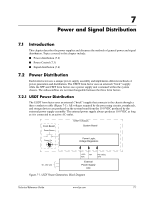
Figure 7-3 shows the power supply cabling for the SFF system.
Connectors not shown to scale.
All + and - values are VDC.
RTN = Return (signal ground)
sns = sense
GND = Power ground
RS = Remote sense
FC = Fan command
FO = Fan off
FSpd = Fan speed
FS = Fan Sink
POK = Power OK (power good)
VccP = +12 for CPU
[1] This row represents pins 13–24 of connector P1
Figure 7-3. SFF Power Cable Diagram
Table 7-2.
SFF 240-Watt Power Supply Unit Specifications
Range/
Tolerance
Min.
Current
Loading [1]
Max.
Current
Surge
Current [2]
Max.
Ripple
Input Line Voltage
90–264 VAC
--
--
--
--
Line Frequency
47–63 Hz
--
--
--
--
Input (AC) Current
--
--
5.0 A
--
--
+3.3 VDC Output
+
4%
0.1 A
15.0 A
15.0 A
50 mV
+5.08 VDC Output
+
3.3 %
0.3 A
17.0 A
17.0 A
50 mV
+5.08 AUX Output
+
3.3 %
0.0 A
3.0 A
3.5 A
50 mV
+12 VDC Output
+
5 %
0.1 A
7.5 A
9.0 A
120 mV
+12 VDC Output (Vcpu)
+
5 %
0.1 A
11.0 A
14.5 A
120 mv
--12 VDC Output
+
10 %
0.0 A
0.15 A
0.15 A
200 mV
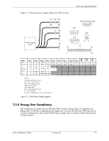
Conn
Pin 1
Pin 2
Pin 3
Pin 4
Pin 5
Pin 6
Pin 7
Pin 8
Pin 9
Pin
10
Pin
11
Pin
12
P1
+5
aux
RTN
+ 5
+5
PS On
RTN
Pwr Gd
+3.3
+3.3
Tach
RTN
Fan
P1 [1]
+12
+5 sns
RTN
+5
+5
+3.3
RTN
+3.3 sns
+3.3
+3.3
RTN
-12
P2
+5
RTN
RTN
+12
P3
RTN
RTN
RTN
VccP
VccP
+12
P4, 5,
7
+3.3
RTN
+5
RTN
+12
Power Supply
Unit
P1
P3
P2
P4
P5
P7
P1
13
1
12
P4, P5, P7
24
1
2
3
4
5
1
2
3
4
P2
P3
1
3
4
6