HP dc73 Technical Reference Guide: HP Compaq dc7800 Series Business Desktop Co - Page 85
Energy Star Compliancy
 |
View all HP dc73 manuals
Add to My Manuals
Save this manual to your list of manuals |
Page 85 highlights
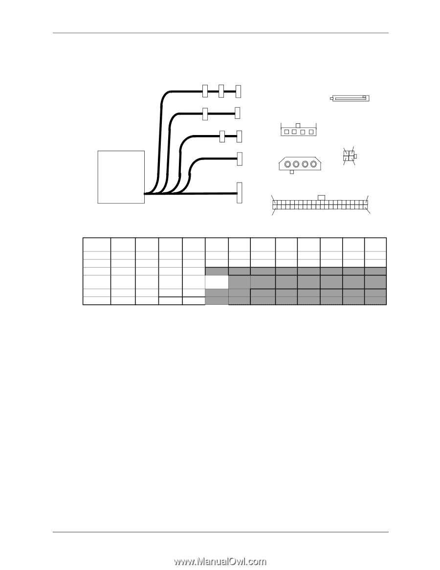
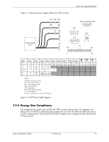
Power and Signal Distribution Figure 7-5 shows the power supply cabling for CMT systems. Power Supply Unit P9 P10 P11 P6 P8 P4 P5 P3 P1 P4, P5, P9, P10, P11 5 4321 P8 432 1 P6 12 34 P1 13 P3 24 13 24 1 12 Conn P1 P1 [1] P3 P4, 5, 9, 10, 11 P6 P8 Pin 1 +3.3 +3.3 RTN +3.3 +12 +5 Pin 2 +3.3 -12 RTN RTN Pin 3 RTN RTN VccP +5.08 Pin 4 +5 PS On VccP RTN Pin 5 RTN RTN +12 Pin 6 +5 RTN Pin 7 RTN RTN RTN RTN +5 RTN RTN +12 Pin 8 POK Open Pin 9 5 aux +5 Pin 10 +12 +5 Pin 11 +12 +5 Pin 12 +3.3 RTN NOTES: Connectors not shown to scale. All + and - values are VDC. RTN = Return (signal ground) GND = Power ground RS = Remote sense POK = Power ok (power good) FC = Fan Command [1] This row represents pins 13-24 of connector P1. Figure 7-5. CMT Power Cable Diagram 7.2.4 Energy Star Compliancy The standard power supply unit for SFF and CMT systems is Energy Star 3.0-compliant. An Energy Star 4.0 (80 Plus-compliant) power supply unit is used for the SFF and CMT form factors in select configurations. The standard USDT power supply unit is compliant with the Energy Star 4.0 specification. Technical Reference Guide www.hp.com 7-5
-
 1
1 -
2
-
3
-
4
-
5
-
6
-
7
-
8
-
9
-
10
-
11
-
12
-
13
-
14
-
15
-
16
-
17
-
18
-
19
-
20
-
21
-
22
-
23
-
24
-
25
-
26
-
27
-
28
-
29
-
30
-
31
-
32
-
33
-
34
-
35
-
36
-
37
-
38
-
39
-
40
-
41
-
42
-
43
-
44
-
45
-
46
-
47
-
48
-
49
-
50
-
51
-
52
-
53
-
54
-
55
-
56
-
57
-
58
-
59
-
60
-
61
-
62
-
63
-
64
-
65
-
66
-
67
-
68
-
69
-
70
-
71
-
72
-
73
-
74
-
75
-
76
-
77
-
78
-
79
-
 80
80 -
 81
81 -
 82
82 -
 83
83 -
 84
84 -
 85
85 -
 86
86 -
 87
87 -
 88
88 -
 89
89 -
 90
90 -
91
-
92
-
93
-
94
-
95
-
96
-
97
-
98
-
99
-
100
-
101
-
102
 |
 |