Hitachi C12LSH Instruction Manual - Page 10
Parts
 |
UPC - 717709010338
View all Hitachi C12LSH manuals
Add to My Manuals
Save this manual to your list of manuals |
Page 10 highlights
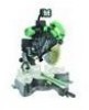
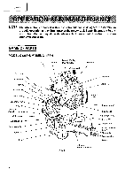
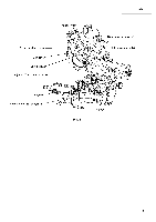
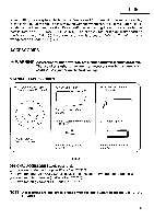
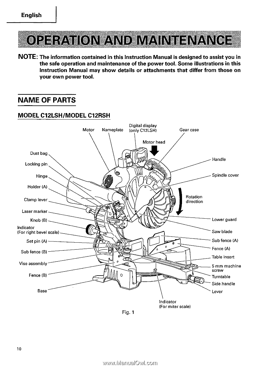
English .4, NOTE: The information contained in this Instruction Manual is designed to assist you in the safe operation and maintenance of the power tool. Some illustrations in this Instruction Manual may show details or attachments that differ from those on your own power tool. NAME OF PARTS MODEL C12LSH/MODEL C12RSH Digital display Motor Nameplate (only C12LSH) Gear case Motor head Dust bag Locking pin Handle Hinge Spindle cover Holder (A) Clamp lever Laser marker Knob (B) Indicator (For right bevel scale) Set pin (A) Sub fence (B) Vise assembly Fence (B) Base UlEI 11/ Fig. 1 Rotation direction 0 Indicator (For miter scale) Lower guard Saw blade Sub fence (A) Fence (A) Table insert 5 mm machine screw Turntable Side handle Lever 10
-
 1
1 -
2
-
3
-
4
-
 5
5 -
 6
6 -
 7
7 -
 8
8 -
 9
9 -
 10
10 -
 11
11 -
 12
12 -
 13
13 -
 14
14 -
 15
15 -
16
-
17
-
18
-
19
-
20
-
21
-
22
-
23
-
24
-
25
-
26
-
27
-
28
-
29
-
30
-
31
-
32
-
33
-
34
-
35
-
36
-
37
-
38
-
39
-
40
-
41
-
42
 |
 |
English
.4,
NOTE:
The
information
contained
in
this
Instruction
Manual
is
designed
to
assist
you
in
the
safe
operation
and
maintenance
of
the
power
tool.
Some
illustrations
in
this
Instruction
Manual
may
show
details
or
attachments
that
differ
from
those
on
your
own
power
tool.
NAME
OF
PARTS
MODEL
C12LSH/MODEL
C12RSH
Dust
bag
Motor
Nameplate
Digital
(only
display
C12LSH)
Gear
case
Motor
head
Handle
Locking
pin
Hinge
Spindle
cover
Holder
(A)
Rotation
Clamp
lever
direction
Laser
marker
Knob
(B)
Lower
guard
Indicator
(For
right
bevel
scale)
Saw
blade
Set
pin
(A)
Sub
fence
(A)
UlEI
11/
0
Fence
(A)
Sub
fence
(B)
Table
insert
Vise
assembly
5
mm
machine
screw
Fence
(B)
Turntable
Side
handle
Base
Lever
Indicator
(For
miter
scale)
Fig.
1
10